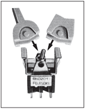
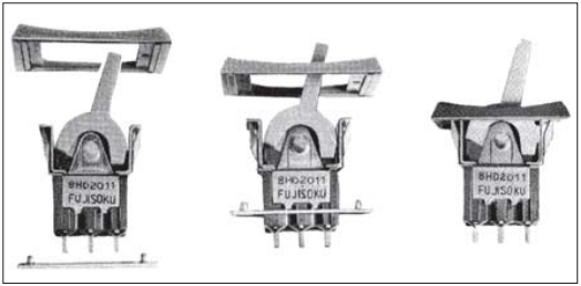
The 8HD Lever & Rocker switch is a dustproof version of the 8H type and is best suited for use in the adverse environment where a lot of dust exists. The lever, rocker, and mounting frame are available in four matted colors. Choose the suitable one for the panel design.
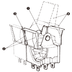
❶Dust proof structure
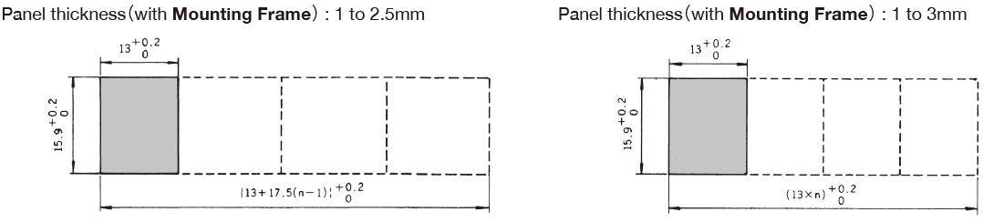
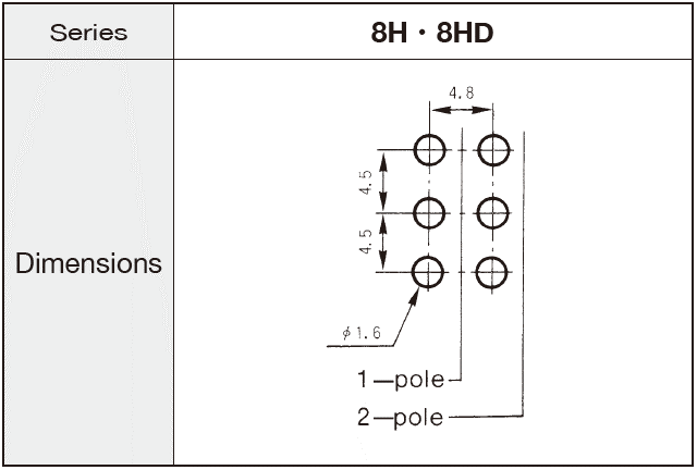
❷Snap-in mounting on panel (The hole layout is same as the 8H.)
❸The side-by-side mounting will not cause gap between switches.
❹Colorful mat-finished levers and rockers that enhance the panel design can be mounted.
Part Number Designation
8
HD
1
01
1
C
- Z
Series
Actuator shape
HD:
Lever / Rocker (Dust proof type)
No. of poles
1: 1 pole
2: 2 poles
Switching function
01: ON-ON
02: ON-OFF-ON
04: (ON)-OFF-(ON)
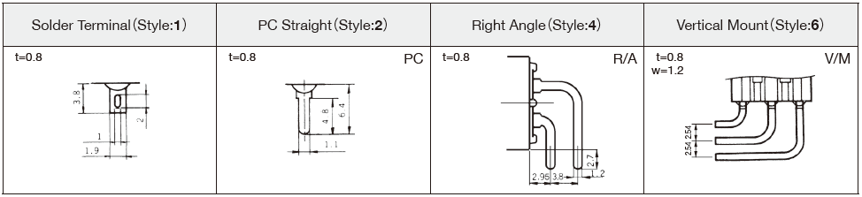
Terminal style
1: Solder
2: PC straight
Contact material / Plating
Blank:
Bs+Ag or Cu+Ag / Silver plated (Ag)
Bs=Brass, Ag=Silver, Cu=Copper
◆Terminals
List of Part Numbers
※
A Part number indicated with a gray-back in the list below was discontinued with an order deadline of Dec. 20, 2023.
Auto Soldering ②275℃ ± 10℃, Max.; 5 seconds, Max. Note that the above-stated soldering conditions should be applied to the PC terminal type only.
◆Flux Cleaning
For the solvent, use the fluorine- or alcohol-based solvent. Solvent: Fluorine or Alcohol type
Since the 8 Switch Series switches are not waterproof-structured, if the PC board is to be cleaned, clean the soldering surface of substrate with a brush so that the switch is not exposed to the cleaning solution.
◆Mounting
Do not bend the terminals before mounting the switch on the PC board.
After mounting the switch, do not place the device in such a way that the device weight will be applied on the knob of the switch.
To fix the PC terminal type, solder it on the PC board after fixing the switch body on the panel with the screw.