


Toggle switch 8E

- ●Um einen Kauf zu tätigen, wenden Sie sich an die Verteiler
oder nutzen Sie den stehenden Online-Shops unten.
Verkaufskanal Überprüfen Sie die Verteiler.- VERKAUFSKANALKlicken Sie hier, um den Verteiler zu überprüfen.


Locking Lever Toggle Switch
-
8E Locking Lever Toggle Switch features a locking device to prevent accidental switch operation. Caps are available in 3 colors. Please refer to "Operation Method" on the next page on instructions on how to operate.
-
Contacts : Silver or gold.
-
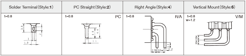
Terminal style : Solder, Straight, Right angle and vertical mount PC terminals.
-
Epoxy resin case : UL94V-0 self-extinguishing epoxy.
-
Actuator styles : Over 30 actuator variations.
-
Insulation between terminal and ground : 4 mm minimum.
-
Prevention of flux entry The epoxy resin seal on bottom of the switch helps prevent the entry of solder and flux.
-
Insulation barrier : Insulation barrier design between poles helps prevent short-circuiting between poles ensuring high reliability.
-
UL Recognized product File No.E43275
-
CSA Certified product File No.LR38341
Part Number Designation
| 8 | E | 1 | 01 | 1 | C | - Z |
|---|---|---|---|---|---|---|
|
Series |
Actuator shape E: Lever-lock toggle |
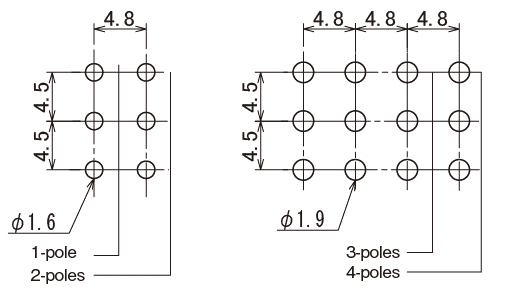
No. of poles 1: 1 pole 2: 2 poles 3: 3 poles 4: 4 poles |
Switching function 01: ON-ON 02: ON-OFF-ON 06: ON-(ON) |
Terminal style 1: Solder 2: PC straight |
Contact material / Plating Blank: Bs+Ag or Cu+Ag / Silver plated (Ag) / Silver plated (Ag) C: Bs+Ag or Cu+Ag / Gold plated (Ni+Au) / Gold plated (Ni+Au) Bs=Brass, Ag=Silver, Cu=Copper, |
◆Terminals
List of Part Numbers
| Part No. | No. of poles | Terminals | SW function | CAD |
|---|---|---|---|---|
| Part No.:8E1011-Z | 1 pole | Solder | ON-ON | |
| Part No.:8E1011C-Z★ | 1 pole | Solder | ON-ON | |
| Part No.:8E1021-Z☆ | 1 pole | Solder | ON-OFF-ON | |
| Part No.:8E1021C-Z★ | 1 pole | Solder | ON-OFF-ON | |
| Part No.:8E1012-Z★ | 1 pole | PC straight | ON-ON | |
| Part No.:8E2011-Z | 2 poles | Solder | ON-ON | |
| Part No.:8E2011C-Z☆ | 2 poles | Solder | ON-ON | |
| Part No.:8E2021-Z★ | 2 poles | Solder | ON-OFF-ON | |
| Part No.:8E2061-Z★ | 2 poles | Solder | ON-(ON) | |
| Part No.:8E2012C-Z★ | 2 poles | PC straight | ON-ON | |
| Part No.:8E3011-Z★ | 3 poles | Solder | ON-ON | |
| Part No.:8E4011-Z★ | 4 poles | Solder | ON-ON |
★: Made to order products
Optional Accessories
| Actuator | Part No. | Color | Ountline dimensions |
|---|---|---|---|
| Color Cap | 140000470058* | Silver | 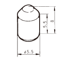 |
| 140000470060 | Red | ||
| 140000470059 | Black |
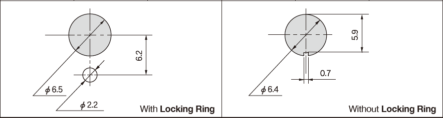
Panel Cut-Out Dimensions
- With Locking Ring:Panel thickness 1.5 mm Max.
- Without Locking Ring:Panel thickness 2.5 mm Max.
PC Hole Layouts
Precautions
Soldering Specifications
- Manual soldering/Device :Solder iron ①420℃ Max. 3 sec. Max.
- Auto soldering/275℃ Max. 6 sec. Max.
- The above-stated soldering conditions shall apply only to switches with straight terminals. Auto soldering is not possible with right-angle terminals. Switches with right-angle terminals should be soldered manually according to the conditions specifi ed in (1) above.
- When soldering two or more terminals to the common land, use the solder resist to isolate the terminals.。
Flux Cleaning
- Solvent : Fluorine or Alcohol type.
- 8A/B/C/D/E/F/J series are not washable. To wash the PC board, clean the soldering surface of the PC board with a brush so that the switch is not exposed to the cleaning solution.
- Cleaning after soldering should be done after the terminal temperature falls to 90℃ or below, or after leaving the switch for fi ve minutes or longer at room temperature.
Mounting
- Do not bend the terminals before mounting the switch on the PC board.
- After mounting the switch, do not place the device in such a way that the device weight will be applied on to the actuator of the switch.
- For switches with straight terminals, solder the switch on the PC board after fi xing the switch on the panel with a nut.
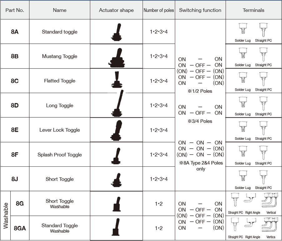
8 Series Toggles Selection Table
Unterlagen
Environmental Data
- ●Die oben genannten Inhalte können ohne vorherige Ankündigung geändert werden.
Produkte
