


Druckaufnehmer (mit Verstärker) PA-838

- ●Um einen Kauf zu tätigen, wenden Sie sich an die Verteiler
oder nutzen Sie den stehenden Online-Shops unten.
Verkaufskanal Überprüfen Sie die Verteiler.- VERKAUFSKANALKlicken Sie hier, um den Verteiler zu überprüfen.


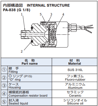
PRESSURE TRANSDUCERS WITH AMP. PA-838
- High corrosion resistance by double diaphragm structure
- Built-in amplifier circuit
- Incorporating temperature compensation function (0 ~ 50 °C)
- Current output mode
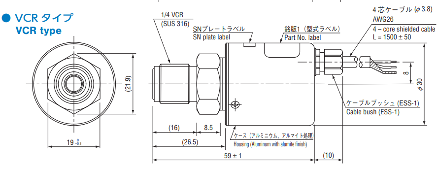
- Available with a ※ VCR® fitting
|
|
Standard specifications
- Unless otherwise specified, the specs are defined at an ambient temperature of 25±5 °C, excitation voltage of 24 V DC and load resistance of 250 Ω.
| Operating temp. range | −20 ~ 70°C |
|---|---|
| Compensated temp. range | 0 ~ 50°C |
| Operating humidity | 35 ~ 85%RH(No condensation) |
| Storage temp. | − 20 ~ 70°C(Atmospheric pressure, humidity 65 %RH maximum) |
| Pressure medium | Corrosive gases/liquids compatible with SUS 316L ※1 |
| Insulation resistance | 100 (500 V DC)MΩ min. |
| Dielectric strength | 500 V AC, 60 s(Leakage current 1 mA maximum) |
| Sealed liquid | Silicone oil |
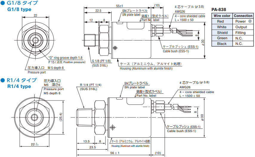
| Pressure port | G 1/8 (PF 1/8)、R 1/4 (PT 1/4)、1/4 VCR® ※2 |
| Net weight | Approx. 140g |
| Supply voltage | 24 ± 10 %V DC |
| Ripple content | 10 % (P-P)maximum |
※1 In case of VCR type, corrosive gases/liquids compatible with SUS 316L and SUS 316.
※2 An “O” ring provided for G1/8 type. (Positive pressure : P15)
※2 An “O” ring provided for G1/8 type. (Positive pressure : P15)
Analog output
- Unless otherwise specified, the specs are defined at an ambient temperature of 25±5 °C, excitation voltage of 24 V DC and load resistance of 250 Ω.
| Rated pressure range | 501G | 102G | 103G |
|---|---|---|---|
| Output current | 4 ~ 20mA | ||
| Zero current | 4 ± 0.2mA (at 25 °C) | ||
| Span current | 16 ± 0.2mA (at 25 °C) | ||
| Load resistance | 0 ~ 500 Ω | ||
| Linearity/Hysteresis | ± 0.5%F.S. | ||
| Thermal error (Reference temp.: 25 °C) |
ZERO:± 0.05/± 0.1%F.S./°C SPAN:± 0.05/± 0.1%F.S./°C |
||
| Response | Approx. 2ms | ||
| Gravitational effect (From vertical position to horizontal position) |
Approx. 0.5%F.S.max. | Approx. 0.3%F.S.max. | Approx. 0.05%F.S.max. |
Model Number Designation
| PA-838- | 102 | A- | 05 |
|---|---|---|---|
|
Series name |
Rated pressure range 501:0 ~ 49.0 kPa {0 ~ 0.5 kgf/cm2} |
Pressure reference G:Gauge |
Thermal error/Fitting 05:± 0.05 % F.S./°C, G 1/8 |
※VCR® is a registered trade name of Cajon Co. CAJON® is a registered trade name of Swagelok Co.
Note: For handling of VCR fittings, please contact a service center of Swagelok Co.
List of model numbers
| Model number | Pressure reference | Thermal error [% F.S./°C] | Fitting | Rated pressure rangekPa {kgf/cm2} | Maximum pressurekPa {kgf/cm2} | Break-down pressurekPa {kgf/cm2} | CAD |
|---|---|---|---|---|---|---|---|
| PA-838-501G-05 | Gauge | ± 0.05 | G 1/8 | 49.0 {0.5} | 98.1 {1} | 147 {1.5} | |
| PA-838-501G-R2 | Gauge | ± 0.05 | R 1/4 | 49.0 {0.5} | 98.1 {1} | 147 {1.5} | |
| PA-838-501G-VCR | Gauge | ± 0.05 | VCR | 49.0 {0.5} | 98.1 {1} | 147 {1.5} | |
| PA-838-501G-10 | Gauge | ± 0.10 | G 1/8 | 49.0 {0.5} | 98.1 {1} | 147 {1.5} | |
| PA-838-102G-05 | Gauge | ± 0.05 | G 1/8 | 98.1 {1} | 196 {2} | 294 {3} | |
| PA-838-102G-R2 | Gauge | ± 0.05 | R 1/4 | 98.1 {1} | 196 {2} | 294 {3} | |
| PA-838-102G-VCR | Gauge | ± 0.05 | VCR | 98.1 {1} | 196 {2} | 294 {3} | |
| PA-838-102G-10 | Gauge | ± 0.05 | G 1/8 | 98.1 {1} | 196 {2} | 294 {3} | |
| PA-838-103G-05 | Gauge | ± 0.05 | G 1/8 | 981 {10} | 1961 {20} | 2942 {30} | |
| PA-838-103G-R2 | Gauge | ± 0.05 | R 1/4 | 981 {10} | 1961 {20} | 2942 {30} | |
| PA-838-103G-VCR | Gauge | ± 0.05 | VCR | 981 {10} | 1961 {20} | 2942 {30} | |
| PA-838-103G-10 | Gauge | ± 0.10 | G 1/8 | 981 {10} | 1961 {20} | 2942 {30} |
Note: For handling of VCR fittings, please contact a service center of Swagelok Co.
Environment Characteristics
| Test item | Test conditions (At 25 ± 5 °C) | Permissible change |
|---|---|---|
| Vibration | 10 ~ 500 Hz, 1.5 mm maximum/98.1 m/s2 3 directions for 2 hours each |
Zero current, Span current: ± 1 %F.S. maximum each |
| Shock | 490 m/s2 3 directions for 3 times each | |
| Pressure cycling | 0 ~ Rated pressure/Rated pressure range 106 cycles | |
| Moisture resistance | 40 °C, 90 ~ 95 %RH, 240 hrs. |
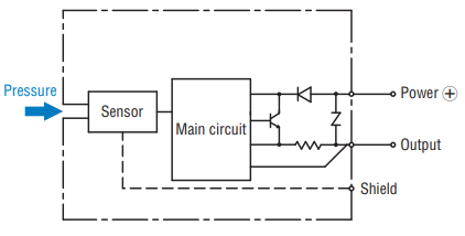
Internal circuit diagram
|
|
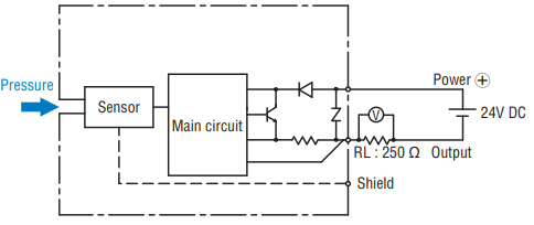
Recommended external schematics
|
|
Outline Dimensions
Unterlagen
- ●Die oben genannten Inhalte können ohne vorherige Ankündigung geändert werden.
Produkte
