


Pressure switch PS30

-
●To buy this product, please go to the following Online Web stores.


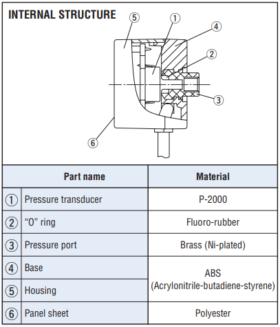
PRESSURE SWITCHES WITH GAUGE
- Optimum for pneumatic equipment and semiconductor manufacturing equipment
- Larger size display and high luminance LED for best visibility
- Eight switch output modes
- Low consumption by nondisplay mode
|
|
MODEL NUMBER DESIGNATION
| PS30- | 102R- | N |
|---|---|---|
|
Series name |
Rated pressure range 102R:−100 ~ 100 kPa 103R:−0.1 MPa ~ 1.00 MPa |
Switch output interface N:NPN open collector P:PNP open collector |
LIST OF MODEL NUMBERS
| Model numbers | Pressure reference | Rated pressure | Switch output interface | CAD |
|---|---|---|---|---|
| PS30-102R-N | Gauge | −100 ~ 100 kPa | NPN | |
| PS30-103R-N | Gauge | −100 ~ 1000 kPa | NPN | |
| PS30-103R-P | Gauge | −100 ~ 1000 kPa | PNP | |
| PS30-102R-P | Gauge | −100 ~ 100 kPa | PNP |
STANDARD SPECIFICATIONS
- Unless otherwise specified, the specs are defined at an ambient temperature of 25 ± 5 °C and excitation voltage of 24 V DC.
| Item | 102R | 103R |
|---|---|---|
| Pressure reference | Gauge | |
| Rated pressure range | − 100 ~ 100kPa | − 100 ~ 1000kPa |
| Maximum pressure | 200kPa | 1500kPa |
| Break-down pressure | 500kPa | 2000kPa |
| Operating temp. range | − 10 ~ 50°C | |
| Compensated temp. range | 0 ~ 50°C | |
| Thermal error | ± 3 %F.S. (0 ~ 50 °C) | |
| Operating humidity | 35 ~ 85%R(No condensation) | |
| Storage temp. | − 20 ~ 70°C(Atmospheric pressure, humidity 65 %RH maximum) | |
| Pressure medium | Non-corrosive gases | |
| Insulation resistance | 100 MΩ minimum(DC 500 V) | |
| Dielectric strength | 500 V AC, 60 s(Leakage current 1 mA maximum) | |
| Pressure port | M5 female screw, “O” ring groove (P8) | |
| Net weight | Approx. 60g(Including 1.5 m cable) | |
| Supply voltage | 12 ~ 24 V ± 10 %(Including ripple voltage) | |
| Consumption current | 40mA maximum | |
Display
| Item | 102R | 103R |
|---|---|---|
| Display element | LED( 2 and 1/2 digit) | |
| Rated display range | − 100 ~ 100kPa | − 0.10 ~ 1.00MPa |
| Display accuracy | ± 1 %F.S. | |
| Resolution | 1 count | |
Switch output
| No. of outputs | 2 | |
|---|---|---|
| Output interface | Open collector output (NPN or PNP) | |
| Display | Output 1 (SW1), Output 2 (SW2) Light on when output is ON | |
| Repeatability | ± 0.3%F.S. maximum | |
| Switch hysteresis | 0 ~ 30 counts(Adjustable) | |
| Switching capacity | 30 V DC 100 mA maximum Short-circuit protection | |
| Residual voltage | 1.2 V maximum (NPN), 2.2 V maximum(PNP) | |
| Response | Approx 5, 25, 250ms(Adjustable) | |
ENVIRONMENTAL CHARACTERISTICS
| Test item | Test conditions | Permissible change |
|---|---|---|
| Vibration | 10 ~ 500 Hz, 98.1 m/s2 or 1.5 mm P-P, 3 directions for 2 hours each | ± 2 %F.S. maximum after test ※1 |
| Shock | 490 m/s2, 3 directions for 3 times each | ± 2 %F.S. maximum after test ※1 |
| Pressure cycling | 0 ~ Rated pressure 106 cycles | ± 2 %F.S. maximum after test ※1 |
| Moisture resistance | 40 °C, 90 ~ 95 %RH, 240 hrs. | ± 2 %F.S. maximum after test ※1 |
| EMC | EMI : EN55011: 2007, A2 : 2007 Group 1, class B EMS : EN61326-1 : 2006 Table 2 |
Switch operating pressure : ± 5 %F.S., maximum during tset ※1 |
※ 1 Change in the pressure indication, switch operating points.
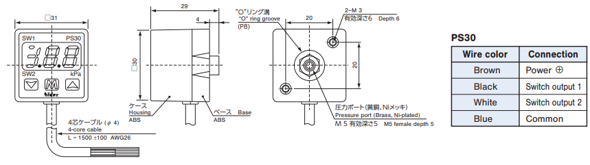
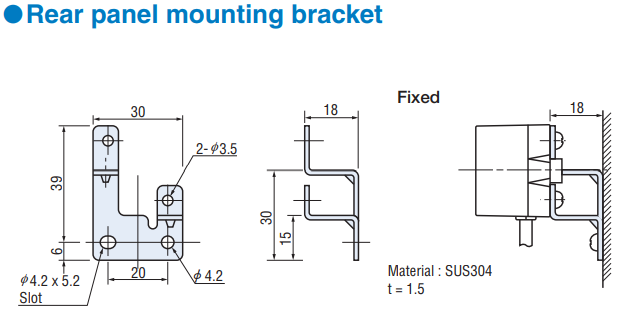
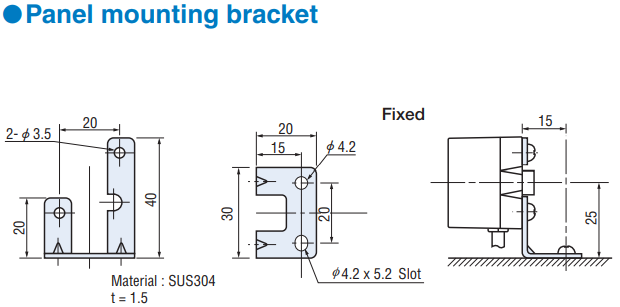
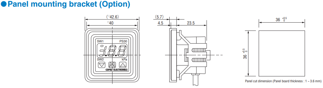
OUTLINE DIMENSIONS
Unless otherwise specified, tolerance : ± 0.5 (Unit : mm)
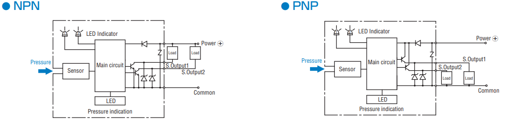
INTERNAL ELECTRICAL SCHEMATICS
SELECTION OF DISPLAY MULTIPLIER
|
|
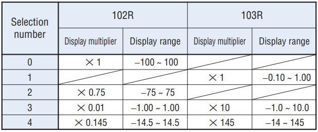
(Note) Diagonal column : No unit can be selected due to resolution and number of digits.
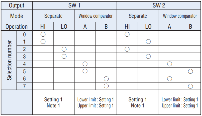
SWITCH OUTPUT MODE
|
|
|
|
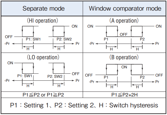
- (Note 1) In the Separte Mode, setting 1 corresponds to SW1, and Setting 2 corresponds to SW2.
- (Note 2) In the Window Comparator Mode, the minimum value for SW1 and SW2 corresponds to Setting 1 and the maximum value corresponds to Settng 2.
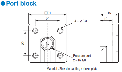
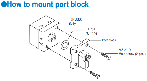
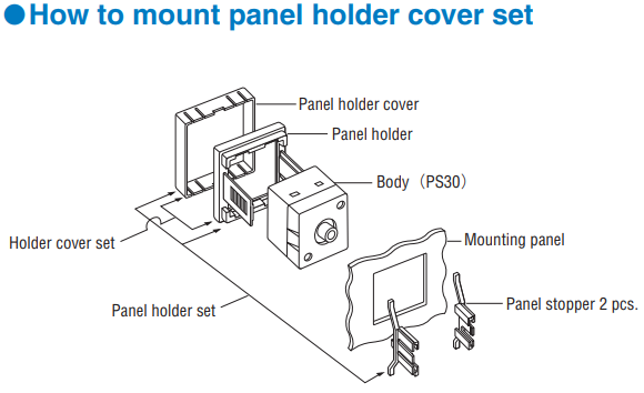
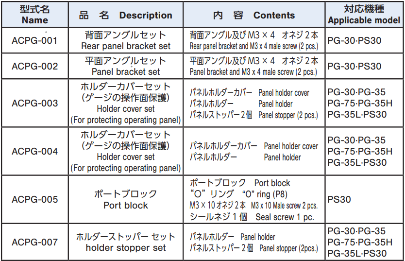
HOW TO MOUNT OPTIONAL ACCESSORIES (Sold separately)
|
|
|
|
|
|
|
|
|
|
Documents
- ●The above contents and descriptions are subject to change without notice.
