


Pressure indicator PZ-30

-
●To buy this product, please go to the following Online Web stores.


Pressure indicator PZ-30
- Pressure indicators separated from sensor
- Can be used with variety of sensors - Wide range of applications such as pneumatic equipment or semiconductor equipment
- Any range of pressure sensors is available
- Low power consumption by non display mode
- Set data protection by panel lock function
STANDARD SPECIFICATIONS
- Unless otherwise specified, the specs are defined at an ambient temperature of 25±5 °C and excitation voltage of 24 VDC.
|
General specifications | Operating temp. range | − 10 ~ 50°C |
|---|---|---|
| Operating humidity | 35 ~ 85%RH | |
| Protection grade | IP40 | |
| Storage temp. | − 20 ~ 70°C | |
| Net weight | Approx. 80g (Including 2 m cable) | |
| Insulation resistance | 100 MΩ minimum | |
| Dielectric strength | 500 V DC 1 minute | |
| Supply voltage | 10.8 ~ 30 V DC(Including ripple percentage)※ | |
| Consumption current | 50 mA maximum | |
|
Imput | Input signal | 1 ~ 5 V (V) / 4 ~ 20 mA (I) |
| Input impedance | 10 kΩ (V) / 250 Ω (I) | |
|
Display | No. of digit | 3 |
| Display element | LED | |
| Display cycle | Approx. 4 times/s | |
| Negative pressure display | “–” LED is ON | |
| Display accuracy | ± 1 %F.S. (Without sensor's error) | |
| Thermal error | ± 0.5 % (0 ~ 50 °C, Reference temp. 25 °C) | |
| Resolution | 1 count | |
|
Switch | Output status | NPN/PNP |
| 2-point output (Transistor, Open collector output) | ||
| Switching capacity | 30 V DC 100 mA maximum | |
| Residual voltage | 1.2 V maximum (NPN), 2.2 V maximum (PNP) | |
| Hysteresis setting | 0 ~ 300 counts Adjustable | |
| Repeatability | ± 0.2 %F.S. ± 1 count | |
| Short circuit protection | With pretection function | |
| Response | Approx. 5 ms (“F – 0”) (Selectable 5 ms ~ 2.5 s) | |
| Thermal error | ± 0.5 %F.S. (0 ~ 50 °C, Refernce temp. 25°C) | |
| State indication | Output 1 (Green LED),Output 2 (Red LED) Lighted when output is ON. | |
| Analog output | Voltage output | 1 ~ 5 V |
| Current output | 4 ~ 20 mA(Load resistance 500 Ω or less ) |
- ※When analog current output type of PZ30 is chosen or when a sensor of current output type is connected, supply voltage is 24 V DC ± 10%
ENVIRONMENTAL CHARACTERISTICS
| Test item | Test conditions | Permissible change |
|---|---|---|
| Vibration | Amplitude 1.5 mm P-P, 10 ~ 55 Hz, 3 directions for 2 hours each (packed) |
Pressure indication, switch operating points and analog output variation : ± 1 %F.S. maximum each after test |
| Shock | 98.1 m/s2 , 3 directions for 3 times each (packed) | |
| Moisture resistance | 40 °C, 90 ~ 95 %RH, 240 hrs | |
| EMC | EMI : EN55011: 2007, A2 : 2007 Group 1, class B EMS : EN61326-1: 2006 Table 2 |
Pressure indication, switch operating pressure and analog output : ± 5 %F.S. maximum during test |
MODEL NUMBER DESIGNATION
| PZ-30- | N | V | S T | I |
|---|---|---|---|---|
|
Series name |
Switch output interface N:NPN open collector P:PNP open collector |
Input signal type V:1 ~ 5 V I:4 ~ 20 mA |
Sensor connection type ST:One-touch type terminal |
Analog output Blank:Voltage output |
LIST OF MODEL NUMBERS
| Model number | Analog output | Switch output type | Input signal type | Sensor connection type | CAD |
|---|---|---|---|---|---|
| PZ-30-NVST | Voltage output | NPN | 1 ~ 5 V | One-touch type terminal | |
| PZ-30-NIST | Voltage output | NPN | 4 ~ 20 mA | One-touch type terminal | |
| PZ-30-PVST | Voltage output | PNP | 1 ~ 5 V | One-touch type terminal | |
| PZ-30-PIST | Voltage output | PNP | 4 ~ 20 mA | One-touch type terminal | |
| ➡PZ-30-NVSTI | Current output | NPN | 1 ~ 5 V | One-touch type terminal | |
| ➡PZ-30-NISTI | Current output | NPN | 4 ~ 20 mA | One-touch type terminal | |
| ➡PZ-30-PVSTI | Current output | PNP | 1 ~ 5 V | One-touch type terminal | |
| ➡PZ-30-PISTI | Current output | PNP | 4 ~ 20 mA | One-touch type terminal | |
| PZ-30-NVCN | Voltage output | NPN | 1 ~ 5 V | Connector type terminal | |
| PZ-30-NICN | Voltage output | NPN | 4 ~ 20 mA | Connector type terminal | |
| PZ-30-PVCN | Voltage output | PNP | 1 ~ 5 V | Connector type terminal | |
| PZ-30-PICN | Voltage output | PNP | 4 ~ 20 mA | Connector type terminal |
※ Marked ➡ is manufactured upon receipt of order basis.
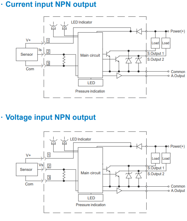
INTERNAL ELECTRICAL SCHEMATICS
⦿Voltage analog output
|
|
|---|
|
|
|---|
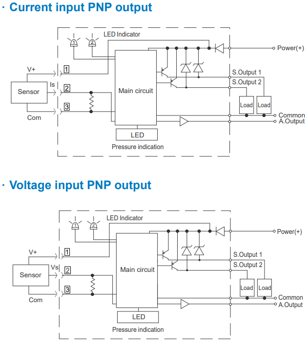
- When connecting the 2-wire type of current output sensors, please do not connect the 3 (Com.) terminal.
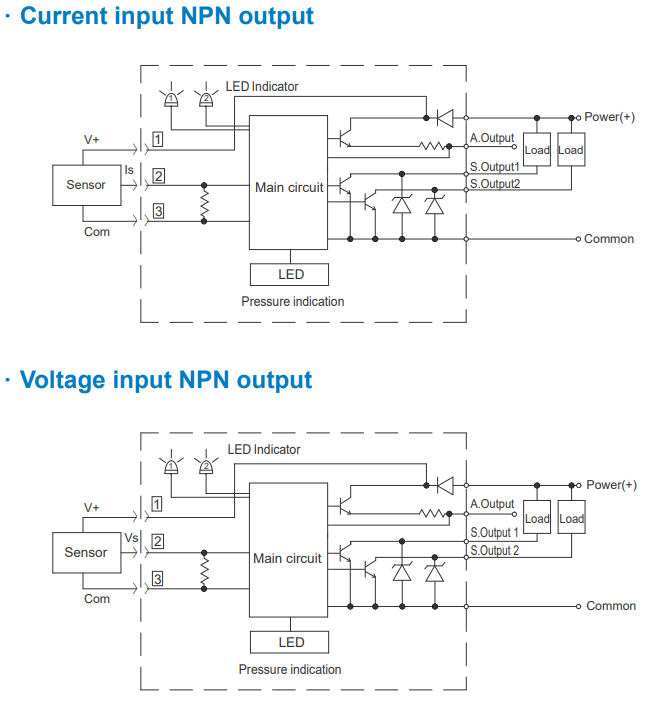
⦿ Current analog output
|
|
|---|
|
|
|---|
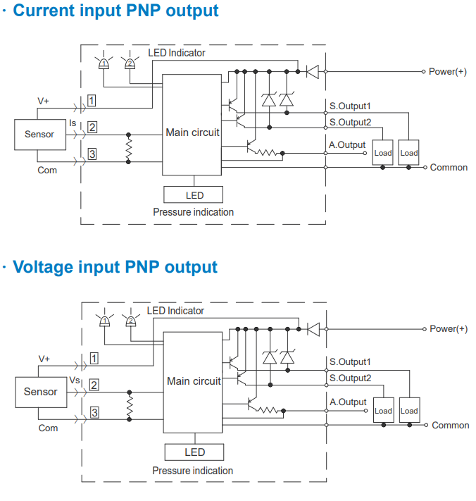
- When connecting the 2-wire type of current output sensors, please do not connect the 3 (Com.) terminal.
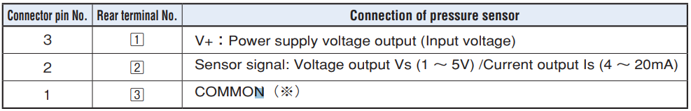
- (Note) Refer to the PIN allocation for the rear terminal number of the PZ-30 and the connector pin terminal number. (Please from the table on dimension drawing)
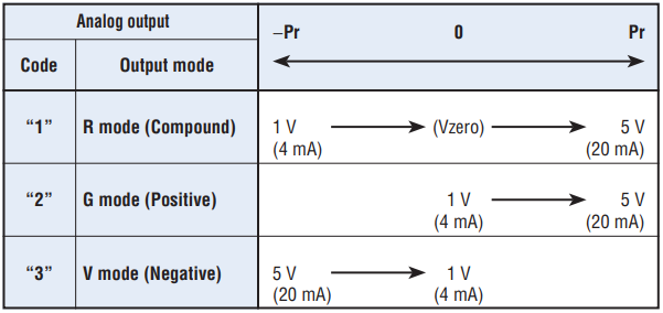
ANALOG OUTPUT MODE
- Analog output setting : The second figure in triple digits LED indicates output mode in the initial setting.
- Output mode is fixed by rated pressure.
|
|
|---|
SWITCH OUTPUT MODE
- Switch output can be set when blinking red LED indicates (SW2) in the intial setting.
- The mode is set at “Separate (H/H), 1” prior to shipment. The mode is initialized at “Separate (L/L), 4” when rated pressure is set at “-12P” or “-12F” (negative pressure).
|
|
|---|

|
|
|---|
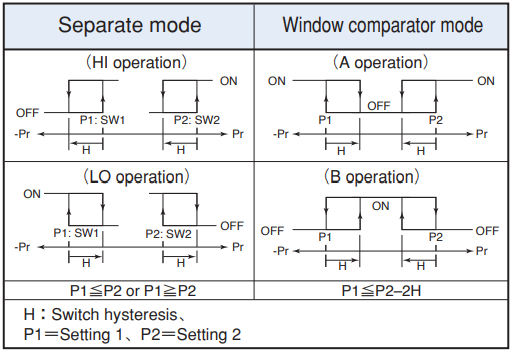
- Note 1. In the Separate Mode, setting 1 corresponds to SW1, and Setting 2 corresponds to SW2.
- Note 2. In the Window Comparator Mode, the minimum value for SW1 and SW2 corresponds to Setting 1 and the maximum value corresponds to Setting 2.
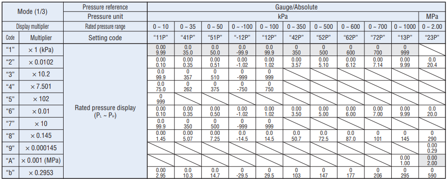
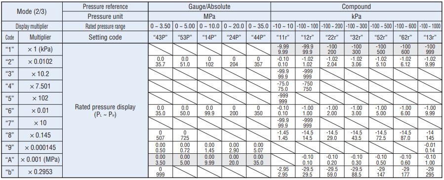
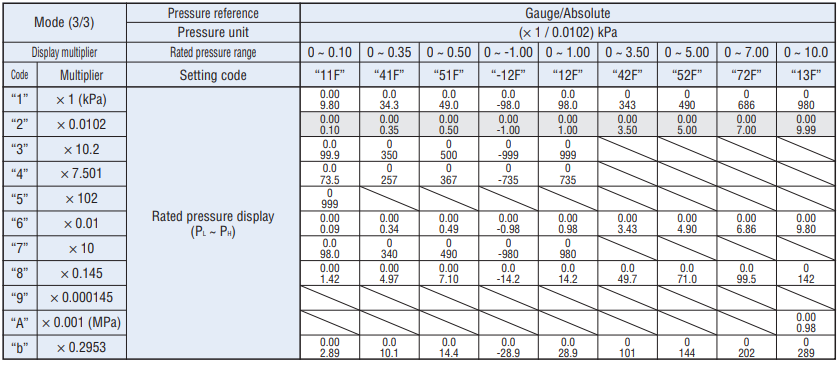
SELECTION OF DISPLAY MULTIPLIER/RATED PRESSURE
● Selection of display multiplier
- Please set any code when blinking red LED indicates negative pressure in the initial setting.
- Display multiplier is set at “1” (kPa) prior to shipment.
● Selection of rated pressure
- Please set any code when blinking red LED indicates negative pressure, SW1, SW2 in the initial setting.
- Rated pressure is set at “12P” (0~100 kPa) prior to shipment.
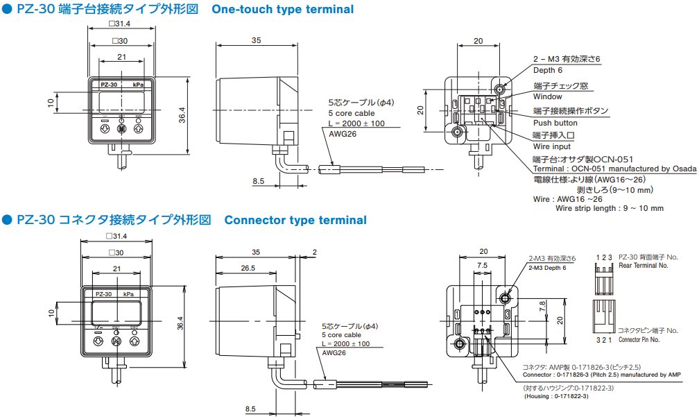
OUTLINE DIMENSION
Unless otherwise specified, tolerance: ± 0.5 (Unit: mm)
|
|
|---|
※ When connecting the 2-wire type of current output sensors, please do not connect the 3 (Com.) terminal.
HOW TO MOUNT OPTIONAL ACCESSORIES
Unless otherwise specified, tolerance: ± 0.5 (Unit: mm)
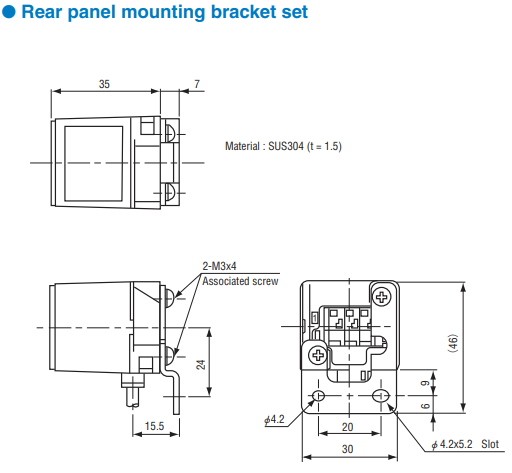
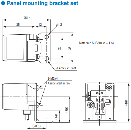
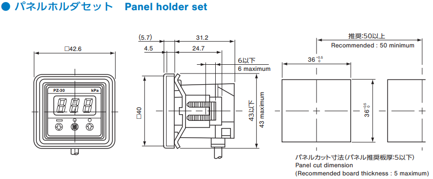
| Name | Series Name | Contents |
|---|---|---|
| Panel holder set | ACPG-003 | Panel holder cover Panel holder Panel stopper (2 pcs.) |
| Holder cover set | ACPG-004 | Panel holder cover Panel holder |
| Holder stopper set | ACPG-007 | Panel holder Panel stopper (2 pcs.) |
| Rear panel bracket set (Z) | ACPG-011 | Rear panel bracket set (Z) and M3 × 4, male screw (2 pcs.) |
| Panel bracket set (Z) | ACPG-012 | Panel panel bracket set (Z) and M3 × 4, male screw (2 pcs.) |
Documents
- ●The above contents and descriptions are subject to change without notice.
