


Rotary switch RS/RG

-
●To buy this product, please contact Sales Reps, Distributors.
long life and high reliability
- RoHS compliant
- P.C.B. mounted, compact size and DIP compatible
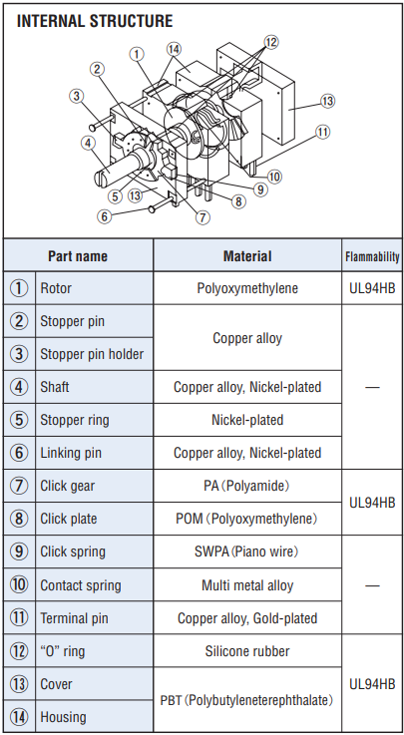
- Protection by “O” ring (contact block) against dust and for cleaning after soldering
- Precious metal alloy wiping type contacts provide a long life (50000 revolutions at no load) and high reliability. (In house comparison)
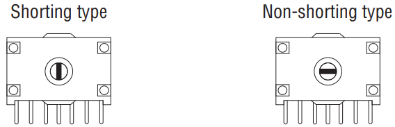
- Both shorting and non-shorting types are available
STANDARD SPECIFICATIONS
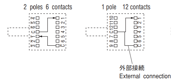
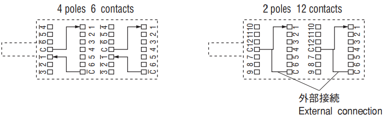
| Circuit type | 1 pole 2~12 contacts (per block) 2 poles 2~6 contacts (per block) |
|---|---|
| Operating temperature range | −40 ~ 85 °C |
| Storage temperature range | −40 ~ 85 °C |
| Sealing | Washable (only contact block, “O” ring sealed) |
| Net weight | Approx. 7 g (1 block) Approx. 13.6 g (2 blocks) Approx. 19.4 g (3 blocks) |
ELECTRICAL CHARACTERISTICS
| Contact rating | 1 VA |
|---|---|
| Maximum current | 1 A |
| Minimum current | 1 μ A |
| Maximum voltage | 30 V |
| Minimum voltage | 20 mV |
| Contact timing | Shorting, Non-shorting |
| Contact resistance | 100 mΩ maximum |
| Insulation resistance | 1000 MΩ (DC500 V) minimum |
| Dielectric strength | AC500 V, 60 s |
| Electrostatic capacity | 4 pF maximum, 10 kHz |
MECHANICAL CHARACTERISTICS
| Adjustment torque | 60 ± 30 mN·m {612 ± 306 gf·cm} |
|---|---|
| Stopper strength | 500 mN·m {5.1 kgf·cm} minimum |
| Stepping angle | 30° |
| Terminal strength | 10 N {1.02 kgf} minimum |
| Solderability | 245 ± 3 °C, 2 ~ 3 s |
| Soldering heat | Flow : 260 ± 3 °C as the temperature in a pot of molten solder, immer sion from head of terminal to backside of board, 5 ~ 6 s, two times maximum Manual soldering: 380 ± 10 °C, 3 ~ 4 s |
ENVIRONMENTAL CHARACTERISTICS
| Load life | 500,000 steps or 50,000 cycles at 6 contacts with no load 200,000 steps or 20,000 cycles at 6 contacts with rated load |
|---|---|
| Vibration | Amplitude 1.5 mm or Acceleration 196 m/s2,10-2000-10 Hz, 3 directions for 4 h each |
| Shock | 980 m/s2, 6 ms 6 directions for 3 times each |
| Humidity (Steady state) | 40 °C, Relative humidity 90 ~ 95 %, 240 h |
| High temperature exposure | 85 °C, 16 h |
| Low temperature exposure | −40 °C, 16 h |
PART NUMBER DESIGNATION
| RS | 1- | 1 | 12 | S- | R | 15 |
|---|---|---|---|---|---|---|
|
Series name RS:Selector RG:Selector (with a ground terminal) |
No. of blocks 1~3:1~ 3 blocks |
No. of poles 1~6:1~6 poles |
No. of contacts 02~12:2~12 contacts |
Contact timing S:Shorting N:Non-shorting |
Shape of shaft R:Round type φ 3.2 mm D:D-cut φ 4.0 mm |
Shaft length 15:15 mm |
※Shaft length of 10 mm or 20 mm is also available.
LIST OF PART NUMBERS
| PART NUMBER | No. of blocks | No. of poles | No. of poles | CAD |
|---|---|---|---|---|
| RS1-102 | 1 | 1 | 02 | |
| RS1-103 | 1 | 1 | 03 | |
| RS1-104 | 1 | 1 | 04 | |
| RS1-105 | 1 | 1 | 05 | |
| RS1-106 | 1 | 1 | 06 | |
| RS1-107 | 1 | 1 | 07 | |
| RS1-108 | 1 | 1 | 08 | |
| RS1-109 | 1 | 1 | 09 | |
| RS1-110 | 1 | 1 | 10 | |
| RS1-111 | 1 | 1 | 11 | |
| RS1-112 | 1 | 1 | 12 | |
| RS1-202 | 1 | 2 | 02 | |
| RS1-203 | 1 | 2 | 03 | |
| RS1-204 | 1 | 2 | 04 | |
| RS1-205 | 1 | 2 | 05 | |
| RS1-206 | 1 | 2 | 06 | |
| RS2-207 | 2 | 2 | 07 | |
| RS2-208 | 2 | 2 | 08 | |
| RS2-209 | 2 | 2 | 09 | |
| RS2-210 | 2 | 2 | 10 | |
| RS2-211 | 2 | 2 | 11 | |
| RS2-212 | 2 | 2 | 12 | |
| RS2-302 | 2 | 3 | 02 | |
| RS2-303 | 2 | 3 | 03 | |
| RS2-304 | 2 | 3 | 04 | |
| RS2-305 | 2 | 3 | 05 | |
| RS2-306 | 2 | 3 | 06 | |
| RS3-307 | 3 | 3 | 07 | |
| RS3-308 | 3 | 3 | 08 | |
| RS3-309 | 3 | 3 | 09 | |
| RS3-310 | 3 | 3 | 10 | |
| RS3-311 | 3 | 3 | 11 | |
| RS3-312 | 3 | 3 | 12 | |
| RS2-402 | 2 | 4 | 02 | |
| RS2-403 | 2 | 4 | 03 | |
| RS2-404 | 2 | 4 | 04 | |
| RS2-405 | 2 | 4 | 05 | |
| RS2-406 | 2 | 4 | 06 | |
| RS3-502 | 3 | 5 | 02 | |
| RS3-503 | 3 | 5 | 03 | |
| RS3-504 | 3 | 5 | 04 | |
| RS3-505 | 3 | 5 | 05 | |
| RS3-506 | 3 | 5 | 06 | |
| RS3-602 | 3 | 6 | 02 | |
| RS3-603 | 3 | 6 | 03 | |
| RS3-604 | 3 | 6 | 04 | |
| RS3-605 | 3 | 6 | 05 | |
| RS3-606 | 3 | 6 | 06 |
※ Verify the above part numbers when placing orders.
※ The above part numbers are all available respectively with the combination of Ground terminal (with or without).
Contact timing (Shorting or Non-shorting), and Shaft shape (Round or D-cut).
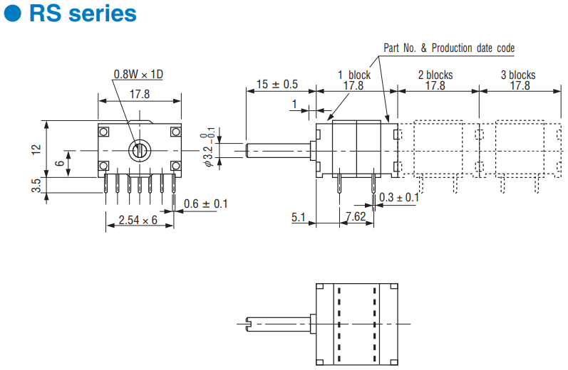
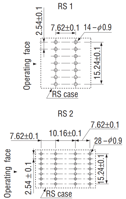
OUTLINE DIMENSIONS
Unless otherwise specified, tolerance: ± 0.3 (Unit: mm)
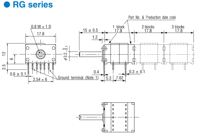
(Note1) A ground terminal is connected electrically to a shaft.
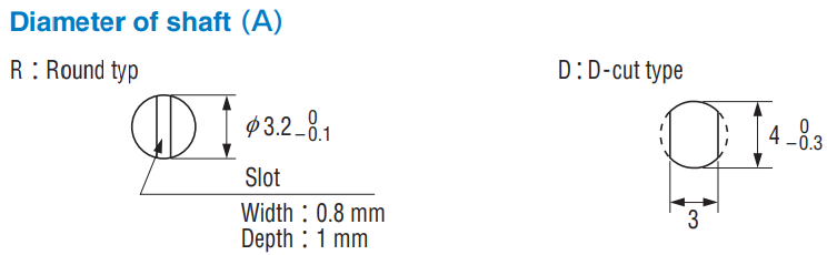
◆〈Shaft slot direction〉
There is a difference in the direction of the slot on the shaft between shorting and non-shorting type.
The location of the shaft of each type when their shafts are fully turned to CCW is shown in the chart below.
Terminal pin layout (Bottom view)
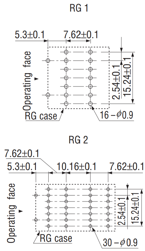
P.C.B. dimensions (Bottom view)
Documents
Environmental Data
- ●The above contents and descriptions are subject to change without notice.
