


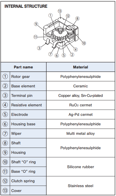
Trimmer potentiometer ST-7

-
●To buy this product, please go to the following Online Web stores.


SURFACE MOUNT CERMET TRIMMERS (3 TURNS)
- RoHS compliant
- Fine adjustment is possible
- Automatic mounting is possible (Taping)
- Flow/reflow soldering is possible
- Sealed construction (Washable)
ELECTRICAL CHARACTERISTICS
| Power ratings | 0.25 W (70 °C) 0 W (125 °C) |
|---|---|
| Nominal resistance range | 50 Ω ~ 1 MΩ |
| Resistance tolerance | ± 20 % |
| Resistance law | Linear law(B) |
| Maximum input voltage | DC200 V or power rating, whichever is smaller |
| Maximum wiper current | 100 mA or power rating, whichever is smaller |
| Effective electrical turn | 2.5 turns |
| End resistance | 1 % or 2 Ω , whichever is greater |
| C.R.V. | 1 % or 3 Ω , whichever is greater |
| Operating temp. range | −55 ~ 120 °C |
| Temp. coefficient | 50 Ω : ± 250 10-6/°C maximum 100 Ω ~ 1 MΩ : ± 100 10-6/°C maximum |
| Insulation resistance | 1000 MΩ minimum (DC500 V) |
| Dielectric strength | AC600 V, 60 s |
| Net weight | Approx. 0.25 g |
MECHANICAL CHARACTERISTICS
| Mechanical turn | 3 turns |
|---|---|
| Operating torque | 5 mN•m {51 gf•cm} maximum |
| Mechanical stop | Clutch action |
| Rotational life | 100 cycles [ΔR/R ≦ ± (2 Ω +3 %)] |
| Thrust to shaft | 5 N {0.51 kgf} minimum |
| Solderability | 245 ± 3 °C, 2 ~ 3 s |
| Shear (Adhesion) | 5 N {0.51 kgf} 10 s |
| Substrate bending | Width 90 mm, bend 3 mm, 5 s, 1 time |
| Pull-off strength | 5 N {0.51 kgf} 10 s |
{ }:Reference only
ENVIRONMENTAL CHARACTERISTICS
| Test item | Test conditions | Specifications |
|---|---|---|
| Thermal shock | -65~125 °C (0.5 h), 5 cycles | [ΔR/R ≦ 2%] [S.S. ≦ 1%] |
| Humidity | -10~65 °C (Relative humidity 80~98%), 10 cycles, 240 h | [ΔR/R ≦ 1%] |
| Shock | 981 m/s2, 6 ms 6 directions for 3 times each | [ΔR/R ≦ 1%] [S.S. ≦ 1%] |
| Vibration | Amplitude 1.52 mm or Acceleration 196 m/s2, 10~2000 Hz, 3 directions, 12 times each | [ΔR/R ≦ 1%] [S.S. ≦ 1%] |
| Load life | 70 °C, 0.25 W, 1000 h | [ΔR/R ≦ 3 %] [S.S. ≦ 1 %] |
| Low temp. operation | -55 °C, 2 h | [ΔR/R ≦ 2%] [S.S. ≦ 2%] |
| High temp. exposure | 125 °C, 250 h | [ΔR/R ≦ 3%] [S.S. ≦ 2%] |
| Immersion seal | 85 °C, 60 s | No leaks (No continuous bubbles) |
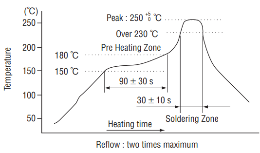
| Soldering heat |
|
[ΔR/R ≦ 1%] |
Δ R/R: Change in total resistance
S.S.: Setting stability
S.S.: Setting stability
〈Reflow profile for soldering heat evaluation〉
MAXIMUM INPUT RATINGS
| Nominal resistance values(Ω) | Resistance code | Maximum input voltage (V) | Maximum wiper current(mA) |
|---|---|---|---|
| 50 | 500 | 3.53 | 70.7 |
| 100 | 101 | 5.00 | 50.0 |
| 200 | 201 | 7.07 | 35.4 |
| 500 | 501 | 11.2 | 22.4 |
| 1k | 102 | 15.8 | 15.8 |
| 2k | 202 | 22.4 | 11.2 |
| 5k | 502 | 35.4 | 7.07 |
| 10k | 103 | 50.0 | 5.00 |
| 20k | 203 | 70.7 | 3.54 |
| 50k | 503 | 112 | 2.24 |
| 100k | 104 | 158 | 1.58 |
| 200k | 204 | 200 | 1.00 |
| 500k | 504 | 200 | 0.40 |
| 1M | 105 | 200 | 0.20 |
PART NUMBER DESIGNATION
| ST-7 | E | T | W | 1 kΩ | (102) |
|---|---|---|---|---|---|
| Series name |
Terminal pin
E:Sn-Cu (Lead-free)
|
Form of packaging
T: Taping (Reel)
Blank: Bulk in plastic bag
|
Product shape (Shape of terminal) |
Resistance code |
Resistance value |
LIST OF PART NUMBERS
| Nominal resistance values | 50Ω, 100Ω, 200Ω, 500Ω, 1kΩ, 2kΩ, 5kΩ, 10kΩ, 20kΩ, 50kΩ, 100kΩ, 200kΩ, 500kΩ, 1MΩ |
|---|
- The above part numbers are all available with the respective combination of<Nominal resistance values>
- Verify the above part numbers when placing orders.
- Taping specification is not sold separately and must be purchased in reel units.
| PART NUMBERS | Shape of terminal | Adjustment position | Form of packaging | Pieces in package | CAD |
|---|---|---|---|---|---|
| ST-7ETA | J-hook | Top adjustment | Taping (reel) | 500 pcs./reel | |
| ST-7EA | J-hook | Top adjustment | Plastic bag | 50 pcs./pack | |
| ST-7ETB | Gull wing | Top adjustment | Taping (reel) | 500 pcs./reel | |
| ST-7EB | Gull wing | Top adjustment | Plastic bag | 50 pcs./pack |
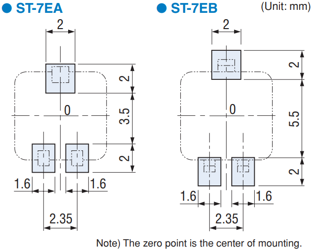
RECOMMENDED P.C.B. PAD OUTLINE DIMENSIONS
OUTLINE DIMENSIONS
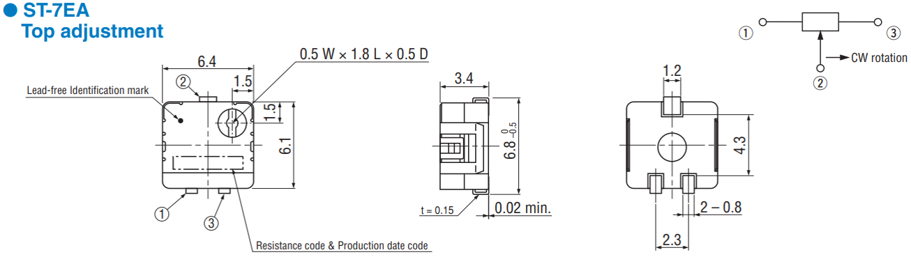
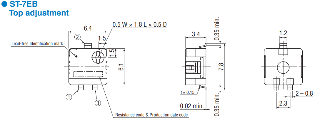
※ The ST-7 series has a different terminal arrangement from the ST-32 and ST-4 series. Pay attention to the location of terminals number 1 and 3. (Resistance decreases when the shaft is turned CCW.)
Documents
Environmental Data
- ●The above contents and descriptions are subject to change without notice.
