


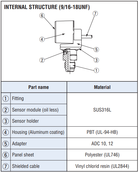
Pressure gauge for high vacuum PG-35L

-
●To buy this product, please go to the following Online Web stores.


Pressure gauge PG-35L
- For high vacuum pressure
- For corrosive gases and liquids compatible with SUS316L stainless steel diaphragm
- Compact • Light weight • Drip-proof structure (30 mm sq • 200 g • IP65)
- Low consumption by nondisplay mode
- Set data protection by panel lock function
|
|
General specifications
- Unless otherwise specified, the specs are defined at an ambient temperature of 25±5 °C and excitation voltage of 12 VDC.
| Model number | 102R | 103R |
|---|---|---|
| Pressure reference | Gauge | |
| Pressure medium | Corrosive gases/liquids compatible with SUS 316L | |
| Rated pressure range | -100~100 kPa | -100~1000kPa |
| Maximum pressure | 200kPa | 1500kPa |
| Break-down pressure | 300 kPa | 2000kPa |
| Operating temp. range | -10~50°C | |
| Compensated temp. range | 0~50°C | |
| Operating humidity | 35~85%RH(No condensation) | |
| Protection grade | IP65 | |
| Type of mounting | Stem mount, Back mount | |
| Pressure Port | R 1/4, G 1/4, VC (9/16 - 18 UNF) | |
| Material of pressure port attachment | SUS 316L | |
| Net weight | Approx. 150g(Including 2 m cable) | |
| Thermal error | ± 3 %F.S. (0~50 °C) | |
| Insulation resistance | 50 MΩ minimum | |
| Dielectric strength | 125 V DC 1 minute | |
| Vacuum working pressure | 1.4×10⁻⁴ Pa abs minimum | |
| Input voltage | 10.8~30 VDC(Including ripple percentage) | |
| Consumption current | 50mA maximum | |
Display
- Unless otherwise specified, the specs are defined at an ambient temperature of 25±5 °C and excitation voltage of 12 VDC.
| Model number | 102R | 103R |
|---|---|---|
| Display element | Full 3-digit LED | |
| Rated display range | −99.9~99.9kPa | −100~999kPa |
| Multiplier settings | Max. 11 settings | |
| Display cycle | Approx. 4 times/s | |
| Negative pressure display | “–” LED is ON | |
| Display accuracy | ± 1 % | |
Switch output
- Unless otherwise specified, the specs are defined at an ambient temperature of 25±5 °C and excitation voltage of 12 VDC.
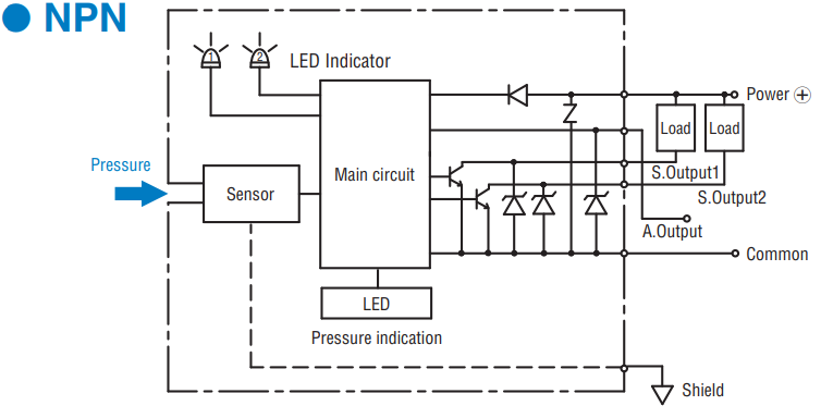
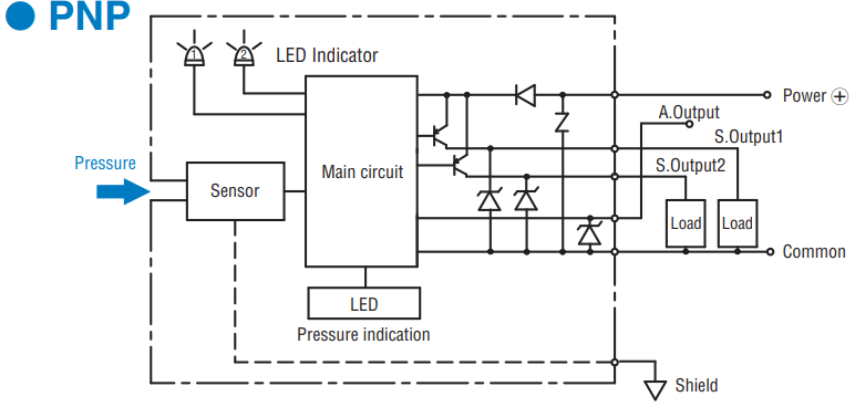
| Output status | NPN/PNP 2-point output (Transistor, Open collector output) |
|---|---|
| Output mode | Separate mode / window comparator mode |
| Switching capacity | 30 V DC 100 mA maximum |
| Residual voltage | 1.2 V maximum (NPN), 2.2 V maximum (PNP) |
| State indication | Output 1 (Green LED),Output 2 (Red LED) Lighted when output is ON. |
| Switch hysteresis | 0 ~ 300 counts(Adjustable) |
| Repeatability | ± 0.2 %F.S. ± 1 count |
| Response | Approx. 5, 25, 250, 2500 ms Adjustable |
Analog output
- Unless otherwise specified, the specs are defined at an ambient temperature of 25±5 °C and excitation voltage of 12 VDC.
| Output mode | 3 modes |
|---|---|
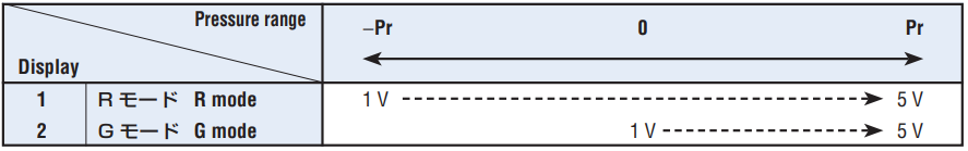
| Output voltage V zero : Pin=0, V span : Pin=0 〜Pin (H) |
1 ~ 5 V (G/V mode ZERO : 1 ± 0.2 V, SPAN : 4 ± 0.2 V R mode ZERO : 3 ± 0.2 V, SPAN : 2 ± 0.2 V ) 103 R (R mode) ZERO : 1.36 ± 0.2 V SPAN : 3.64 ± 0.2 V |
| Impedance | 10 kΩ |
| Resolution | 1/204(Approx. 4.9mV/ Approx.0.123% F.S.) |
ENVIRONMENTAL CHARACTERISTICS
| Test item | Test conditions | Permissible change |
|---|---|---|
| Vibration | 10 ~ 500 Hz, 98.1 m/s2 or 1.5 mm P-P, 3 directions for 2 hours each |
Amount of analog output fluctuation is permitted by adding conversion error of 20 mV. |
| Shock | 490 m/s2 , 3 directions for 3 times each | |
| Moisture resistance | 40 °C, 90 ~ 95 %RH, 240 hrs | |
| Pressure cycling | 0 ~ Rated pressure, 106 cycles | |
| EMC | EMI : EN55011: 2007, A2 : 2007 Group 1, class B EMS : EN61326-1: 2006 Table 2 |
Pressure indication, switch operating pressure and analog output : ± 5 %F.S. maximum during test ※ 1 |
※ 1Change in the pressure indication, switch operating points and analog output.
MODEL NUMBER DESIGNATION
| PG - 35L- | 102 | R- | N | VC | B |
|---|---|---|---|---|---|
|
Series name |
Pressure range 102:-100~100 kPa103:-100~1000 kPa |
Pressure reference R:Compound pressure (Negative pressure~Positive pressure) |
Switch output interface N:NPN open collector P:PNP open collector |
Fitting R:1/4 G2:G 1/4 VC:9/16 - 18 UNF (Gusket joint) |
Port Blank:Stem mount B:Back mount |
LIST OF MODEL NUMBERS
| Model number | Rated pressure range | Pressure reference | Fitting | Port F | Switch output interface | CAD |
|---|---|---|---|---|---|---|
| PG-35L-102R-NR2 | −100~100 kPa | Gauge | R2 (R 1/4) | Stem mount | NPN | |
| ➡PG-35L-102R-PR2 | −100~100 kPa | Gauge | R2 (R 1/4) | Stem mount | PNP | |
| PG-35L-103R-NR2 | −100~1000 kPa | Gauge | R2 (R 1/4) | Stem mount | NPN | |
| ➡ PG-35L-103R-PR2 | −100~1000 kPa | Gauge | R2 (R 1/4) | Stem mount | PNP | |
| PG-35L-102R-NG2 | −100~100 kPa | Gauge | G2 (G 1/4) | Stem mount | NPN | |
| ➡PG-35L-102R-PG2 | −100~100 kPa | Gauge | G2 (G 1/4) | Stem mount | PNP | |
| PG-35L-103R-NG2 | −100~1000 kPa | Gauge | G2 (G 1/4) | Stem mount | NPN | |
| ➡PG-35L-103R-PG2 | −100~1000 kPa | Gauge | G2 (G 1/4) | Stem mount | PNP | |
| PG-35L-102R-NVC | −100~100 kPa | Gauge | VC (9/16-18 UNF) | Stem mount | NPN | |
| ➡PG-35L-102R-PVC | −100~100 kPa | Gauge | VC (9/16-18 UNF) | Stem mount | PNP | |
| PG-35L-103R-NVC | −100~1000 kPa | Gauge | VC (9/16-18 UNF) | Stem mount | NPN | |
| ➡PG-35L-103R-PVC | −100~1000 kPa | Gauge | VC (9/16-18 UNF) | Stem mount | PNP | |
| PG-35L-102R-NR2B | −100~100 kPa | Gauge | R2 (R 1/4) | Back mount | NPN | |
| ➡PG-35L-102R-PR2B | −100~100 kPa | Gauge | R2 (R 1/4) | Back mount | PNP | |
| PG-35L-103R-NR2B | −100~1000 kPa | Gauge | R2 (R 1/4) | Back mount | NPN | |
| ➡ PG-35L-103R-PR2B | −100~1000 kPa | Gauge | R2 (R 1/4) | Back mount | PNP | |
| PG-35L-102R-NG2B | −100~100 kPa | Gauge | G2 (G 1/4) | Back mount | NPN | |
| ➡PG-35L-102R-PG2B | −100~100 kPa | Gauge | G2 (G 1/4) | Back mount | PNP | |
| PG-35L-103R-NG2B | −100~1000 kPa | Gauge | G2 (G 1/4) | Back mount | NPN | |
| ➡PG-35L-103R-PG2B | −100~1000 kPa | Gauge | G2 (G 1/4) | Back mount | PNP | |
| PG-35L-102R-NVCB | −100~100 kPa | Gauge | VC (9/16-18 UNF) | Back mount | NPN | |
| ➡PG-35L-102R-PVCB | −100~100 kPa | Gauge | VC (9/16-18 UNF) | Back mount | PNP | |
| PG-35L-103R-NVCB | −100~1000 kPa | Gauge | VC (9/16-18 UNF) | Back mount | NPN | |
| ➡PG-35L-103R-PVCB | −100~1000 kPa | Gauge | VC (9/16-18 UNF) | Back mount | PNP |
Marked ➡ is manufactured upon receipt of order basis.
INTERNAL ELECTRICAL SCHEMATICS
|
|
|
|
SELECTION OF DISPLAY MULTIPLIER
- The last digit/letter represents the selection code : Blinking red LED indicates negative pressure.
|
|

- Diagonal column: Display multiplier cannot be selected due to resolution and number of digits.
- (Selection code is not indicated either.) Selection code is set at “A” prior to shipment.
ANALOG OUTPUT MODE
- Selection code is set at “G” prior to shipment
|
|
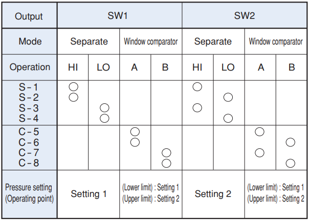
SWITCH OUTPUT MODE
|
|
|
|
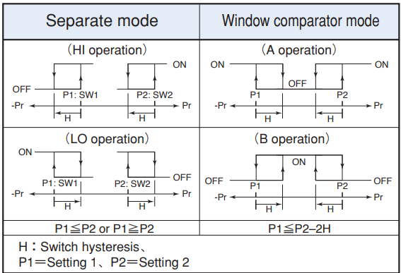
- Note 1. In the Separate Mode, setting 1 corresponds to SW1, and Setting 2 corresponds to SW2.
- Note 2. In the Window Comparator Mode, the minimum value for SW1 and SW2 corresponds to Setting 1 and the maximum value corresponds to Setting 2.
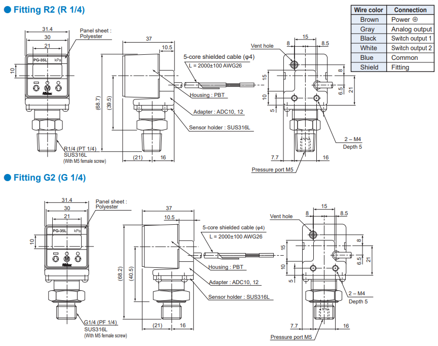
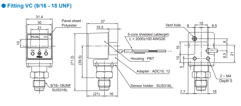
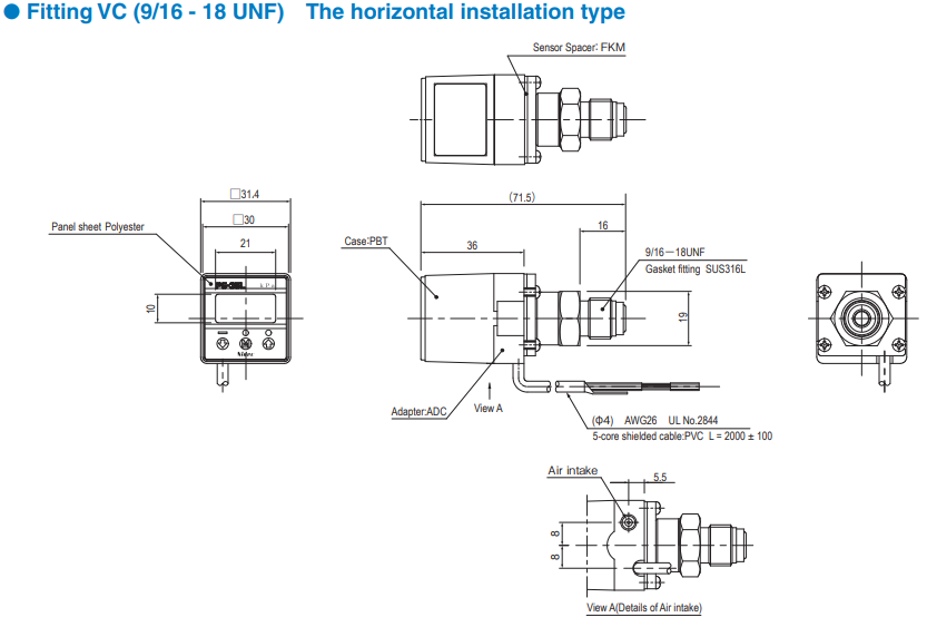
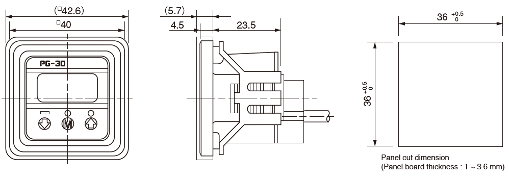
OUTLINE DIMENSIONS
Unless otherwise specified tolerance : ± 0.5 (Unit: mm)
Others
- Tube at atmospheric pressure intake
If there is any possibility that the sensor may become wet with oil or water, which may enter the case through the air intake, connect a silicon tube, or similar, to the intake and position the end of the tube in a suitably safe place. Be sure not to bend the tube or block the end of the tube. - Piping
Use a wrench on a hexagon of fitting part. Do not hold the main body when tightening.
Customization
We also offer customized solutions. Please contact your local sales office for details.
| Model number | Shape and other customization |
|---|---|
| PG 35L-103R-NVC-056 | Use no oil |
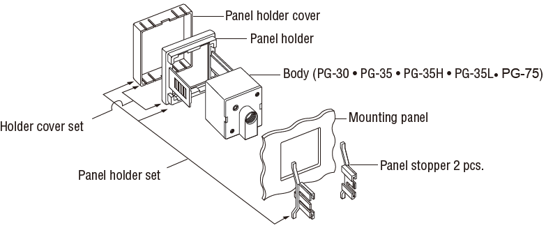
ACCESSORIES (Sold separately)
| Name | Series name | Contents | Applicable model |
|---|---|---|---|
| Panel holder set | ACPG-003 | Panel holder cover Panel holder Panel stopper (2pcs.) |
PG-30 · PG-35 · PG-75 · PG-35H · PG-35L |
| Holder cover set (For protecting gauge operating panel) |
ACPG-004 | Panel holder cover Panel holder |
PG-30 · PG-35 · PG-75 · PG-35H · PG-35L |
HOW TO MOUNT OPTIONAL ACCESSORIES (Sold separately)
◆PG-30 • PG-35 • PG-35H • PG-35L • PG-75 Panel cut holder set & holder cover set
◆Panel holder cover set
Documents
- ●The above contents and descriptions are subject to change without notice.
