


Pressure switch PS60

-
●To buy this product, please go to the following Online Web stores.


PRESSURE SWITCHES WITH GAUGE
- Applicable for negative through positive pressure with 10 mm thick slim housing
- Suitable for use in clean rooms with easy-to-use push keys
- Plug-in connector is provided for easy installation and maintenance
- Space saving and mountable on DIN rails
- Data protection by panel lock system
- Low consumption by nondisplay mode
|
|
General specifications
- Unless otherwise specified, the specs are defined at an ambient temperature of 25 ± 5 °C and excitation voltage of 24 V DC.
| Item | 102R | 302R | 103R |
|---|---|---|---|
| Pressure reference | Gauge | ||
| Rated pressure range | −100 ~ 100kPa | −100 ~ 300kPa | −100 ~ 1000kPa |
| Maximum pressure | 200kPa | 600kPa | 1500kPa |
| Break-down pressure | 500kPa | 1000kPa | 2000kPa |
| Operating temp. range | −10 ~ 50°C | ||
| Compensated temp. range | 0 ~ 50°C | ||
| Operating humidity | 35 ~ 85%RH(No condensation) | ||
| Storage temp. | −20 ~ 70°C(Atmospheric pressure, humidity 65 %RH maximum)) | ||
| Pressure medium | Non-corrosive gases | ||
| Insulation resistance | 100 MΩ min.(500 V DC) | ||
| Thermal error | ± 3 %F.S. (0 ~ 50 °C) | ||
| Dielectric strength | 500 V AC, 60 s(Leakage current 1 mA maximum) | ||
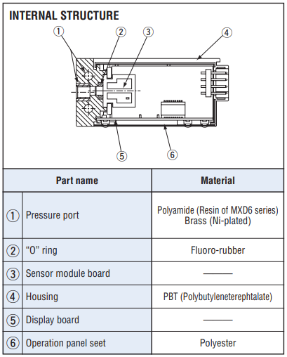
| Pressure port | M5 Female screw | ||
| Net weight | Approx. 50g(Includihg cable) | ||
| Supply voltage | 12 ~ 24 V ± 10 %(Including ripple percentage) | ||
| Consumption current | 30mA max. | ||
| Accessories | PS60 cable, DIN rail adaptor | ||
Switch output
- Unless otherwise specified, the specs are defined at an ambient temperature of 25 ± 5 °C and excitation voltage of 24 V DC.
| No. of outputs | 2 |
|---|---|
| Output interface | Open collector output (NPN or PNP) |
| Setting method | Adjustable by panel switch |
| Adjustable range | −110 kPa (approx.) ~ “999” counts |
| Display | Red LED ON |
| Repeatability | ± 0.3 %F.S. maximum |
| Switch hysteresis | 0 ~ 30 counts |
| Switching capacity | 30 V 100 mA maximum |
| Residual voltage | 1.2 V maximum(NPN), 2.2V maximum (PNP) |
| Response | Approx. 5, 25, 250ms |
Display
- Unless otherwise specified, the specs are defined at an ambient temperature of 25 ± 5 °C and excitation voltage of 24 V DC.
| Item | 102R | 302R | 103R |
|---|---|---|---|
| Display element | 3-digit LED | ||
| Rated display range | −100 ~ 100 kPa | −100 ~ 300 kPa | −0.10 ~ 1.00 MPa |
| Display accuracy 0 〜 50℃ (Reference temp. 25℃) |
± 1 %F.S. | ||
| Resolution | 1 count | ||
ENVIRONMENTAL CHARACTERISTICS
| Test item | Test conditions | Permissible change |
|---|---|---|
| Vibration | 10 ~ 500 Hz, 1.5 mm maximum/98.1 m/s2 , 3 directions for 2 hours each |
Pressure indication and switch operating output : ± 2 %F.S., maximum each after test |
| Shock | 196 m/s2 , 3 directions for 3 times each | |
| Moisture resistance | 40 °C, 90 ~ 95 %RH, 240 hrs | |
| Pressure cycling | 0 ~ Rated pressure, 106 cycles | |
| EMC | EMI : EN55011: 2007, A2 : 2007 Group 1, class B EMS : EN61326-1 : 2006 Table 2 |
Pressure indication and switch operating output, alalog output : ± 5 %F.S., maximum during test |
MODEL NUMBER DESIGNATION
| PS60- | 102 | R- | N | M | CN |
|---|---|---|---|---|---|
|
Series name |
Rated pressure range 102:−100 ~ 100 kPa 103:−100 ~ 1000 kPa 302:−100 ~ 300 kPa |
Pressure reference R:Compound pressure (Negative pressure ~ Positive pressure) |
Switch output interface N:NPN open collector P:PNP open collector |
Pressure port M:M5 female screw |
Signal / power cable pullout method CN:Connector pullout |
LIST OF MODEL NUMBERS
| Model number | Rated pressure | Pressure port | Output interface | CAD |
|---|---|---|---|---|
| PS60-102R-NMCN | −100 ~ 100 kPa | M5 Female screw | NPN | |
| PS60-102R-PMCN | −100 ~ 100 kPa | M5 Female screw | PNP | |
| PS60-302R-NMCN | −100 ~ 300 kPa | M5 Female screw | NPN | |
| PS60-302R-PMCN | −100 ~ 300 kPa | M5 Female screw | PNP | |
| PS60-103R-NMCN | −100 ~ 1000 kPa | M5 Female screw | NPN | |
| PS60-103R-PMCN | −100 ~ 1000 kPa | M5 Female screw | PNP |
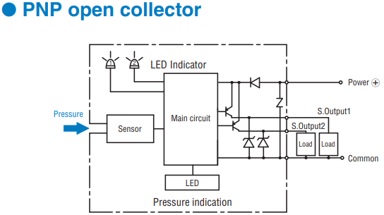
CIRCUIT DIAGRAMS
|
|
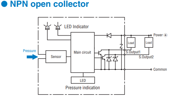
|
|
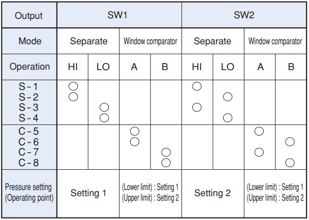
SWITCH OUTPUT MODE
|
|
|
|
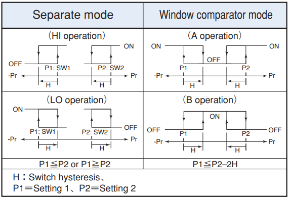
- Note 1. In the Separate Mode, setting 1 corresponds to SW1, and Setting 2 corresponds to SW2.
- Note 2. In the Window Comparator Mode, the minimum value for SW1 and SW2 corresponds to Setting 1 and the maximum value corresponds to Setting 2.
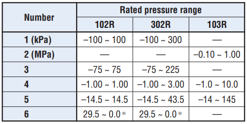
DISPLAY RANGE
- Display range can be selected as the table.
- Note) “–” on the table indicates that it is not selectable in relation to resolution and display lines.
- ※ : In terms of setting display range, please verify the default mode.
|
|
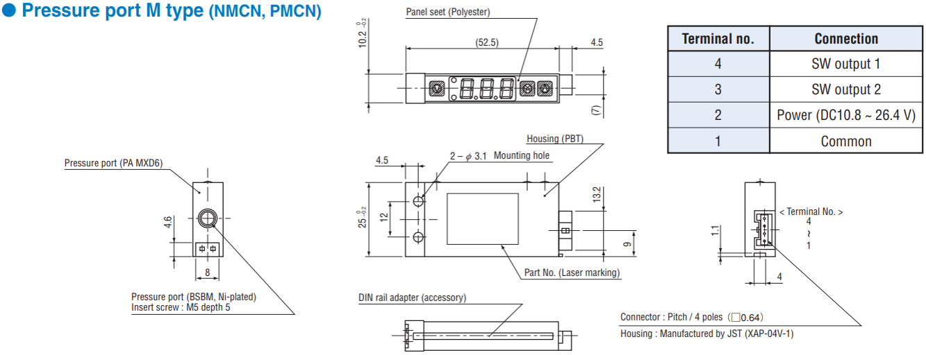
OUTLINE DIMENTIONS
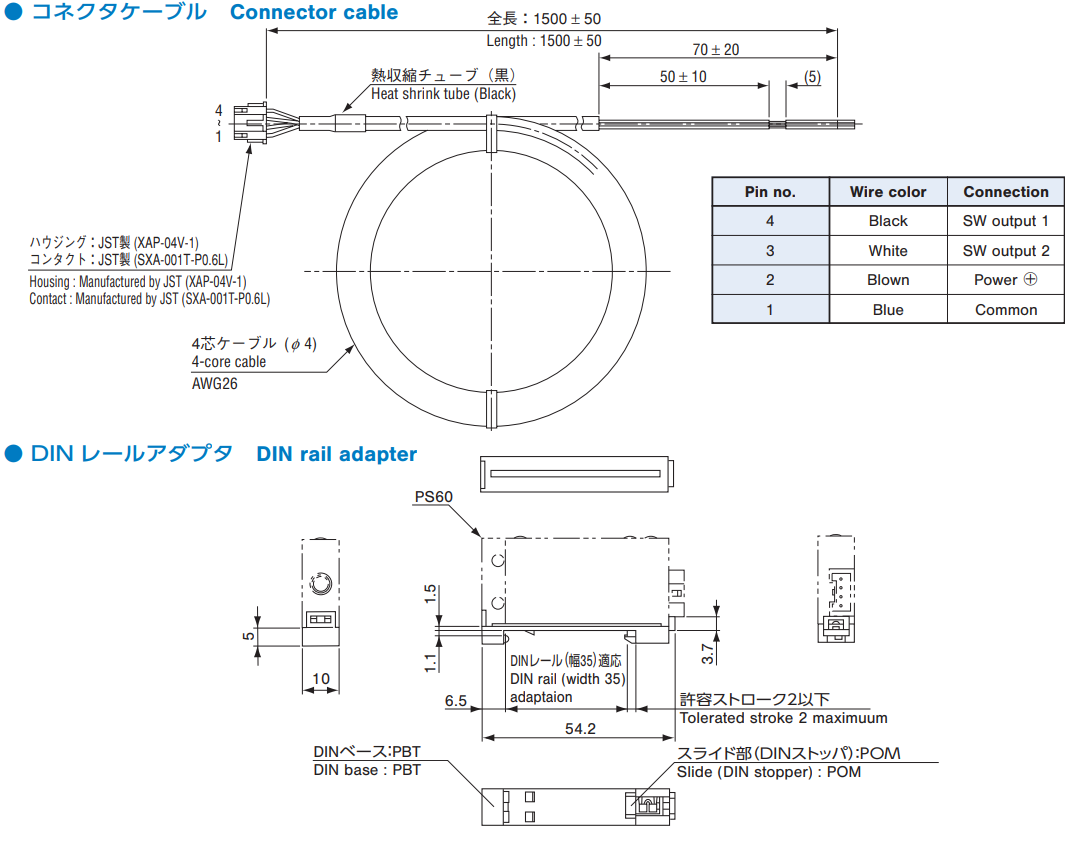
Accessories
Documents
- ●The above contents and descriptions are subject to change without notice.
