


Treiber TF029B-1001-D

- ●Um einen Kauf zu tätigen, wenden Sie sich an die Verteiler
oder nutzen Sie den stehenden Online-Shops unten.
Verkaufskanal Überprüfen Sie die Verteiler.- VERKAUFSKANALKlicken Sie hier, um den Verteiler zu überprüfen.


Dedicated to the Micro Blower TF029 series
- The drivers enable users to vary the speed of the motor by adjusting the control voltage of the external input.
- Contents of the kit are Driver board and Harness.
- Wire Harness: for Driver-Power connection
STANDARD SPECIFICATIONS
- Unless otherwise specified, the environmental conditions are 23°C±5°C, normal humidity, and atmospheric pressure range 90 to 106kPa
| No. | Item | Item | |||
|---|---|---|---|---|---|
| 1 | Configuration | Drivers(Dedicated to the Micro Blower TF029 series) | |||
| 2 | Rotational Speed | 36,000 r/min(reference value) at 2.0kPa, 100L/min | |||
| 3 | Power Consumption | 14.9W max. at 2.0kPa, 100L/min | |||
| 4 | Rated Voltage | DC 24 V±10% | |||
| 5 | Max. Input Current | 2.0 A max.(DC) (Excluding inrush current) | |||
| 6 | Readiness time | 5sec max.From power on to motor start | |||
| 7 | Running Current | 0.62 A max. at 2.0kPa, 100L/min | |||
| 8 | Weight | 40 g max. | |||
| 9 | Operating Temperature | -10~ 50 °C | |||
| 10 | Operating Humidity Range | 10~ 90 %RH (No condensation) | |||
| 11 | Storage Temperature | -20~ 60 °C | |||
| 12 | Storage Humidity Range | 10~ 90 %RH (No condensation) | |||
| 13 | Resistance to Vibration | To meet the Spec after the following test | Non-operating | ||
| Kind of Vibration | Frequency Rang | ||||
| Frequency Range | 10 ~ 22Hz amplitude 1mm | ||||
| 22 ~ 50Hz, 19.6m/s2 (2G acceleration) | |||||
| Sweep | to-and-fro, approx. 5min. | ||||
| Test Time | X, Y, Z directions, 60min. each | ||||
| 14 | Resistance to Shock | To meet the Spec after the following test | Non-operating | ||
| Acceleration | 294m/s2(30G) | ||||
| Pulse Width | 6ms | ||||
| Shock Waven | Semi-sinusoidal wave | ||||
| Number of Shock | X, Y, Z, directions, once per each direction | ||||
INTERFACE
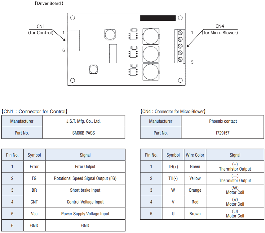
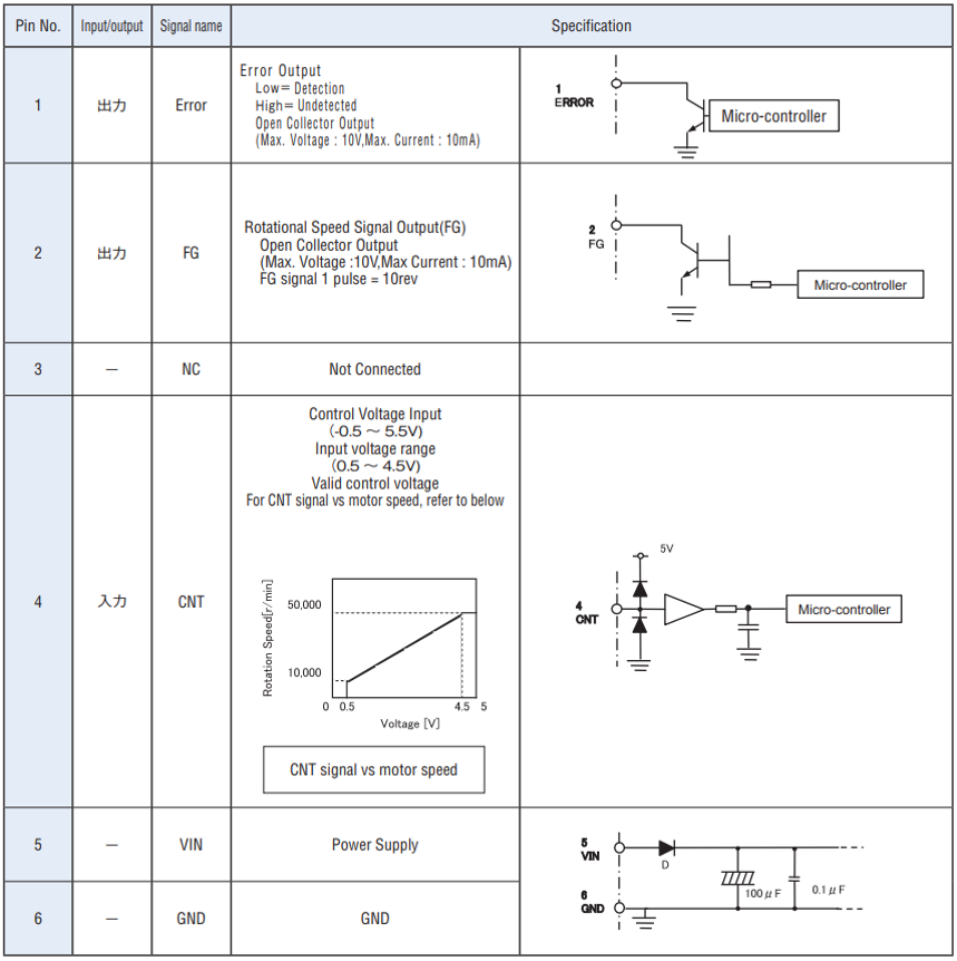
CN1(CONNECTOR FOR CONTROL) SPECIFICATIONS
POWER SUPPLY,CONTROLLER VOLTAGE INPUT
※To avoid high in rush current and protect driver, follow below chart at power up and CNT signal input sequence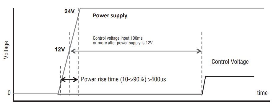
- ① Keep power rise time(10 → 90%) is more than 400us. If high rate power is applied, in rush current will be so huge.
- ② Wait more than 100ms after power exceeds 12V to apply CNT signal.
PROTECTIVE FUNCTIONS
| Protective Functions | Description |
|---|---|
| Over current | If over voltage detected at power line, Blower will be stopped. Recover: Check and correct supply voltage. |
| Over current | When power line current exceeds 3A, fuse will be opened and cut off power. Recover: Contact with us. |
| High temperature | When high Turbo Fan internal temperature, outputs error signal and turn it off. If error is detected, LED will blink at 1Hz Recover: Wait until it's cooled down and try again. (If not solved, contact with us.) |
| Over speed | When motor speed exceeds limit, outputs error signal and turn it off. If error is detected, LED will blink at 1Hz Recover: Reduce CNT signal voltage and try again.(If not solved, contact with us.) |
| Over current at motor coil | When motor coil current exceeds limit, outputs error signal and turn it off. Recover: Check motor operation condition. |
| Abnormal voltage of supplied power | When power supply voltage exceeds limit, outputs error signal and turn it off. If error is detected, LED will blink at 1Hz Recover: Check power supply voltage and try again |
| Abnormal operation | When any failure is detected on driver, outputs error signal and turn it off. If error is detected, LED will blink at 4Hz Recover: Check power supply voltage and try again.(If not solved, contact with us) |
- Normal operation : Green LED is ON. (Red is OFF.)
- Abnormal condition : Red LED is blinking. (Green is turned off.)
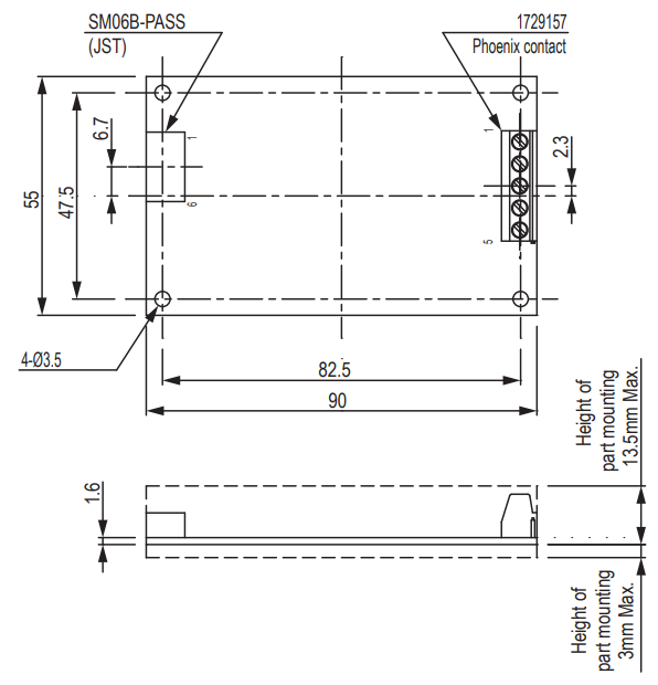
OUTLINE DIMENSIONS
 |
|---|
Unterlagen
- ●Die oben genannten Inhalte können ohne vorherige Ankündigung geändert werden.
Produkte
