


Pushbutton switch 8W-N

- ●Um einen Kauf zu tätigen, wenden Sie sich an die Verteiler unten.
Verkaufskanal Überprüfen Sie die Verteiler.- VERKAUFSKANALKlicken Sie hier, um den Verteiler zu überprüfen.
Snap-in Pushbutton Switches
-
The 8W Snap-in Pushbutton switch is an 8R Soft Touch Pushbutton switch with a 12 mm square button and a
mounting frame. -
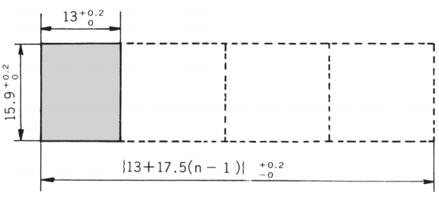
The panel cut-out dimensions are the same as the 8H series Lever & Rocker switcheswhich enables side-by-side mounting.
-
Buttons and mounting frames are available in 4 colors.
-
Silver or gold-plated contacts
-
Epoxy resin case UL94V-0 self-extinguishing epoxy.
-
Insulation between terminal and ground: 4 mm minimum.
-
Prevention of flux entry The epoxy resin seal on bottom of the switch helps prevent short-circuiting between poles ensuring high reliability
-
Insulation barrier: Insulation barrier design between poles helps prevent short-circuiting between poles ensuring high reliability.
Specifications
| Rating | Silver plated:3A 125VAC (Resistive load) Gold plated :60mA 30VDC max. (Resistive load) |
|---|---|
| Initial contact resistance | Silver plated:10mΩ max.(1A 2~4VDC) Gold plated:20mΩ max.(5mA 200μVAC) |
| Initial dielectric strength | 1,000VAC 1 minute |
| Initial insulation resistance | 1,000MΩ min. (500VDC) |
| Electrical life | 25,000 operations(50,000 operations:Gold plate) |
| Operating temperature range | -20℃~+85℃ |
| Storage temperature range | -40℃~+85℃ |
| Operating force | 8W102■-N-Z:2.94±0.98N 8W202■-N-Z:4.9±1.96N |
Part Numbering
| 8 | W | 1 | 01 | 1 | B | - | Z |
| Series code |
Actuator shape N:Standard P:Splash proof Y:Mustang R:Soft Touch W:Snap-in |
Number of poles 1: 1 2: 2 |
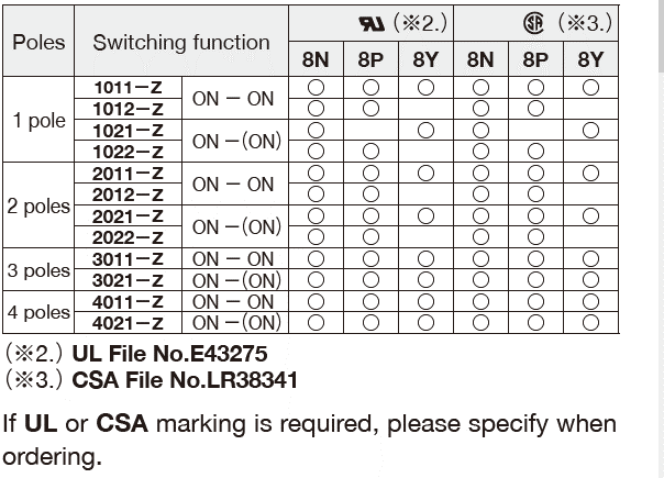
Switching function 01: ON-ON 02: ON-(ON) |
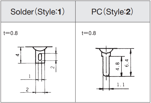
Terminal style 1: Solder 2: PC/Straight |
Contact material /Plating None:Bs+Ag or Cu+Ag/Ag B: Bs or Cu/Ni+Au C:Bs+Ag or Cu+Ag/Ni+Au |
Note :Some combinations may not be available. Please check the "Tableof Part Numbers" for each series.
List of part numbers
| Part Number | Number of poles | Switching function | Terminal style | CAD |
|---|---|---|---|---|
| 8W1021-N-Z | 1pole | ON -( ON) | Solder | |
| ★8W2021-N-Z | 2poles | ON -( ON) | Solder | |
| ★8W1022B-N-Z | 1pole | ON - ON | PC Straight |
Terminal Styles
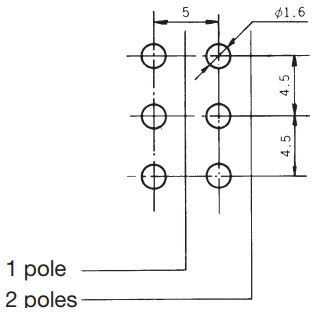
PC Hole Layouts
Panel Cut-Out Dimensions
Panel thickness(with Mounting Frame) : 1 mm to 2.5 mm
ボタン、取付枠の取付方法
※Specify part number of Button and Mounting Frame when ordering.
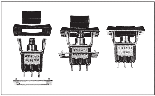
Standard Accessories
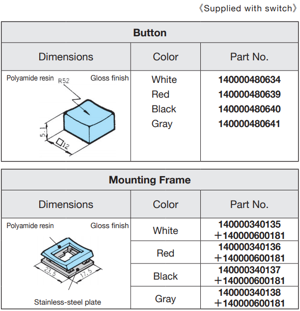
※Please specify the Button and the Mounting Frame when ordering.
Soldering Specifications
- Manual soldering
Device:Solder iron
①420℃ Max. 3 sec. Max. - Auto soldering
②The above-stated soldering conditions shall apply only to switches with straight terminals. Auto soldering is not possible with right-angle terminals.
Switches with right-angle terminals should be soldered manually according to the conditions specified in (1) above. - When putting the switches through an aging process after they were soldered onto the printing board or after installed into a complete end product, be sure to remove the buttons ofthe switches.,
Mounting
- Do not bend the terminals before mounting the switch on the PC board.
- After mounting the switch, do not place the device in such a way that the device weight will be applied on to the actuator of the switch.
- For switches with straight terminals, solder the switch on the PC board after fixing the switch on the panel with a nut.
Flux Cleaning
- Solvent : Fluorine or Alcohol type.
- 8A/B/C/D/E/F/J/S series are not washable. To wash the PC board, clean the soldering surface of the PC board
with a brush so that the switch is not exposed to the cleaning solution.
UL-Recognized, CSA certified Products
Unterlagen
Environmental Data
- ●Die oben genannten Inhalte können ohne vorherige Ankündigung geändert werden.
Produkte
