


Illuminated pushbutton switch LTR/LTM
-

LTR/LTM
-
LTR/LTM
- ●Um einen Kauf zu tätigen, wenden Sie sich an die Verteiler
oder nutzen Sie den stehenden Online-Shops unten.
Verkaufskanal Überprüfen Sie die Verteiler.- VERKAUFSKANALKlicken Sie hier, um den Verteiler zu überprüfen.


Ultra-Miniature Illuminated Pushbutton Switches
-
Full Surface Illumination (LTM2, LTMG2, LTR2 Series Miniature, low-cost switch with full surface illumination by LED. Buttons available in square shape (7.5/10mm sq.) and round shape (7.5/10mm dia.) in 3 colors (Red, Green, Yellow). Non-illuminated switches also available (LTM1, LTMG1, LTR1 series).
-
Two Types of Contacts LTR series: Conductive rubber contact for soft tactile feel. LTM/LTMG series: Metal contact for sharp tactile feel.
-
PC Board Mount Terminal pitch is in inches (multiples of 2.54 mm) for all models. The unique terminal shape prevents the terminals from coming loose from the PC board during dip soldering.
-
Enhanced Resistance to Soldering Heat Improved terminal structure protects the contacts from soldering heat. In addition, each pole has two terminals which can be used as a jumper wire.
Specifications
| Rating | LTR : 10mA 12VDC max. 10μ A Min.
LTM: 1VA max.( 50mA max.48VDC max) 0.5mA min. LTMG:1VA Max.(50mA max.48VDC max.) 10 μ A min. |
|---|---|
| Initial Contact Resistance |
LTR: 500Ω max.(1mA 2VDC at 1.47N{ 150gf}) LTM:100mΩ max (1.5mA 200μ VAC at 1.96N{ 200gf}) |
| Dielectric Strength | 250VAC 1 minute |
| Insulation Resistance | 100MΩ min( 100VDC) |
| Electrical Life | LTR:100,000 operations LTM:300,000 operations |
| Contact Bounce |
LTR:3 msec. max. ( Initial value) |
| Operating Force (at peak force) |
LTR:0.98±0.39N |
| Travel |
LTR:1 mm |
| Operating Temperature Range | -25~+70℃ |
| Storage Temperature Range | -40~+70℃ |
Part Number Designation
| LT | M | G | 2- | 01- | L2 |
|---|---|---|---|---|---|
|
Series |
Type of Contact M: Metal contact R: Conductive rubber contact |
Contact Plating Blank: Silver plated G: Gold plated |
Structure 1: Non-illuminated 2: Illuminated |
LED luminance 01: Normal 31: High |
LED Color (Plaease refer below) |
LED specification
- LTM2-##-## / LTMG2-##-## / LTR2-##-##
| Part No. (##-##) | LED color | Luminance | Forward current (IF) | Forward V (VF)/nom. | Forward V (VF)/ max. | Reverse voltage (VR) |
|---|---|---|---|---|---|---|
| 01-L2 | Red | Normal | 30 mA | 2.0 VDC | 2.5 VDC | 5 VDC |
| 01-L5 | Green | Normal | 25 mA | 2.2 VDC | 2.5 VDC | 5 VDC |
| 01-L8 | Yellow | Normal | 30 mA | 2.1 VDC | 2.5 VDC | 5 VDC |
| 31-L2 | Red | High | 30 mA | 1.95 VDC | 2.5 VDC | 5 VDC |
| 31-L5 | Green | High | 30 mA | 3.2 VDC | 4.0 VDC | 5 VDC |
| 31-L8 | Yellow | High | 30 mA | 2.0 VDC | 2.5 VDC | 5 VDC |
List of Part Numbers
| Part number | Type of Contact | LED Color | Contact Plating | LED Luminance | CAD |
|---|---|---|---|---|---|
| LTM1-01 | Metal contact | ― | Silver plated | ― | |
| LTM2-01-L2 | Metal contact | Red | Silver plated | Normal | |
| LTM2-01-L5 | Metal contact | Green | Silver plated | Normal | |
| LTM2-01-L8 | Metal contact | Yellow | Silver plated | Normal | |
| LTM2-31-L2 | Metal contact | Red | Silver plated | High | |
| LTM2-31-L5 | Metal contact | Green | Silver plated | High | |
| LTM2-31-L8 | Metal contact | Yellow | Silver plated | High | |
| LTMG1-01 | Metal contact | ― | Gold plated | ― | |
| ★LTMG2-01-L2 | Metal contact | Red | Gold plated | Normal | |
| ★LTMG2-01-L5 | Metal contact | Green | Gold plated | Normal | |
| ★LTMG2-01-L8 | Metal contact | Yellow | Gold plated | Normal | |
| LTR1-01 | Conductive rubber contact | ― | Gold plated | ― | |
| LTR2-01-L2 | Conductive rubber contact | Red | Gold plated | Normal | |
| LTR2-01-L5 | Conductive rubber contact | Green | Gold plated | Normal | |
| LTR2-01-L8 | Conductive rubber contact | Yellow | Gold plated | Normal | |
| LTR2-31-L2 | Conductive rubber contact | Red | Gold plated | High | |
| LTR2-31-L5 | Conductive rubber contact | Green | Gold plated | High | |
| LTR2-31-L8 | Conductive rubber contact | Yellow | Gold plated | High |
Optical Accessories
1. Color buttons
| Size | Illuminated type or Non | Luminance | Color | Part No. | Outline dimenions |
|---|---|---|---|---|---|
| □7.5 ㎜ | Without LED | ― | Black | 140007480168 | 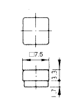 |
| Gray | 140007480169 | ||||
| White | 140007480170 | ||||
| Ivory | 140007480171 | ||||
| Red | 140007480172 | ||||
| Green | 140007480174 | ||||
| Blue | 140007480173 | ||||
| With LED | Normal | Clear | 140007480422 | ||
| Red clear | 140007480205 | ||||
| Green clear | 140007480206 | ||||
| Yellow clear | 140007480207 | ||||
| High | Clear | 140007480554 | |||
| Red clear | 140007480551 | ||||
| Green clear | 140007480552 | ||||
| Yellow clear | 140007480553 | ||||
| Φ7.5 ㎜ | Without LED | ― | Black | 140007480178 | 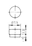 |
| Gray | 140007480179 | ||||
| White | 140007480180 | ||||
| Ivory | 140007480181 | ||||
| Red | 140007480182 | ||||
| Green | 140007480184 | ||||
| Blue | 140007480183 | ||||
| With LED | Normal | Clear | 140007480451 | ||
| Red clear | 140007480208 | ||||
| Green clear | 140007480209 | ||||
| Yellow clear | 140007480210 | ||||
| □10 ㎜ | Without LED | ― | Black | 140007480188 | 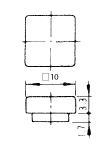 |
| Gray | 140007480189 | ||||
| White | 140007480190 | ||||
| Ivory | 140007480191 | ||||
| Red | 140007480192 | ||||
| Green | 140007480194 | ||||
| Blue | 140007480193 | ||||
| With LED | Normal | Clear | 140007480505 | ||
| Red clear | 140007480211 | ||||
| Green clear | 140007480212 | ||||
| Yellow clear | 140007480213 | ||||
| High | Clear | 140007480562 | |||
| Red clear | 140007480559 | ||||
| Green clear | 140007480560 | ||||
| Yellow clear | 140007480561 | ||||
| Φ10 ㎜ | Without LED | ― | Black | 140007480198 | 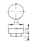 |
| Gray | 140007480199 | ||||
| White | 140007480200 | ||||
| Ivory | 140007480201 | ||||
| Red | 140007480202 | ||||
| Green | 140007480204 | ||||
| Blue | 140007480203 | ||||
| With LED | Normal | Clear | 140007480506 | ||
| Red clear | 140007480214 | ||||
| Green clear | 140007480215 | ||||
| Yellow clear | 140007480216 |
2. Dot illuminated color buttons
| Size | Luminance | LED color | Button color | Part No. | Outline dimensions |
|---|---|---|---|---|---|
| □10 ㎜ | Normal | Clear | Black | 140007480452 | 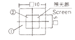 |
| Gray | 140007480453 | ||||
| White | 140007480454 | ||||
| Φ10 ㎜ | Normal | Clear | Black | 140007480459 | 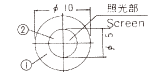 |
| Gray | 140007480460 | ||||
| White | 140007480461 |
3. Mounting frames
| Applicable size | Color | Part No. | Outline dimensions |
|---|---|---|---|
| for □7.5 ㎜ | Black | 140000340170 | 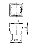 |
| Gray | 140000340179 | ||
| White | 140000340180 | ||
| Ivory | 140000340181 | ||
| for Φ7.5 ㎜ | Black | 140000340171 | 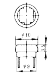 |
| Gray | 140000340182 | ||
| White | 140000340183 | ||
| Ivory | 140000340184 | ||
| for □10 ㎜ | Black | 140000340168 | 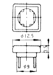 |
| Gray | 140000340173 | ||
| White | 140000340174 | ||
| Ivory | 140000340175 | ||
| for Φ10 ㎜ | Black | 140000340169 | 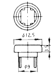 |
| Gray | 140000340176 | ||
| White | 140000340177 | ||
| Ivory | 140000340178 |
Precautions
◆Soldering
| Series | LTM | LTR |
|---|---|---|
|
Manual soldering |
380 ℃ Max. 3 sec. Max. |
380 ℃ Max. 3 sec. Max. |
| Auto soldering | 275 ℃ Max. 6 sec. Max. |
265 ℃ Max. 6 sec. Max. |
- Preheating in the fl ow line should be 80~120℃ , 120 sec. max.
- Do not dip solder the switches with color buttons or mounting frames attached. Soldering heat may deform the accessories or cause ingress of fl ux.
◆Flux Cleaning
- Solvents : Fluorine or Alcohl type
- LTM and LTR series are not washable. To wash the PC board, clean the soldering surface of the PC board with a brush so that the switch is not exposed to the cleaning solution.
- After soldering, wait until the temperature of the terminals cool down to 90℃ or below or until the parts are exposed to room temperature for more than 5 min. before washing.
◆Ambient Conditions
- In case of switches with silver-plated contacts, do not use in an environment where there is corrosive gas such as sulfuric or ammonia gas which may aff ect the silver plating.
- LTM and LTR series are open-structure switches and should not be used in a dusty environment.
Environmental Data
- ●Die oben genannten Inhalte können ohne vorherige Ankündigung geändert werden.
Produkte
