


Trimmpotentiometer ST-4

- ●Um einen Kauf zu tätigen, wenden Sie sich an die Verteiler
oder nutzen Sie den stehenden Online-Shops unten.
Verkaufskanal Überprüfen Sie die Verteiler.- VERKAUFSKANALKlicken Sie hier, um den Verteiler zu überprüfen.


Surface Mount Cermet Trimmers (Single Turn)
FeaturesFeatures
- RoHS compliant
- Wide variety (7 types) to choose from
- Automatic mounting is possible (Taping)
- Flow/reflow soldering is possible
- Sealed construction (Washable)
- Stopper structure prevents terminal pin from being open.
- Cross slot rotor suitable for automatic adjustment
- In this series, chemSHERPA downloads are available,
which can be used for REACH-SVHC surveys, etc. - Click to go to the List of Part Numbers below for download
ELECTRICAL CHARACTERISTICS
| Nominal resistance range | 10 Ω ~ 2 MΩ |
|---|---|
| Resistance tolerance | ± 20 % |
| Power ratings | 0.25 W (70 °C), 0 W (125 °C) |
| Resistance law | Linear law (B) |
| Maximum input voltage | DC200 V or power rating, whichever is smaller |
| Maximum wiper current | 100 mA or power rating, whichever is smaller |
| Effective electrical angle | 210 ° (1 turn) |
| End resistance | 1 % or 2 Ω , whichever is greater |
| C.R.V. | 1 % or 3 Ω , whichever is greater |
| Operating temp. range | -55 ~ 125 °C |
| Temp. coefficient | 10 Ω ~ 50 Ω: ± 250 10-6/°C maximum 100 Ω ~ 2 MΩ: ± 100 10-6/°C maximum |
| Insulation resistance | 1000 MΩ minimum (DC500 V) |
| Dielectric strength | AC 500 V, 60 s |
| Net weight | Approx. 0.12 g (ST-4EA, EB, EC, ED, EF) Approx. 0.22 g (ST-4EG, EH) |
MECHANICAL CHARACTERISTICS
| Mechanical angle | 240° (1 turn) |
|---|---|
| Operating torque | 10 mN·m {102 gf·cm} maximum |
| Stop strength | 30 mN·m {306 gf·cm} minimum |
| Rotational life | 100 cycles [ΔR/R ≦ ± (2 Ω +3%)] |
| Thrust to rotor | 5 N {0.51 kgf} minimum |
| Solderability | 245 ±3°C, 2~3 s |
| Shear (Adhesion) | 5 N {0.51 kgf} 10 s |
| Substrate bending | Width 90 mm, bend 3 mm, 5 s, 1 time |
| Pull-off strength | 5 N {0.51 kgf} 10 s |
ENVIRONMENTAL CHARACTERISTICS
| Test item | Test conditions | Specifications |
|---|---|---|
| Thermal shock | -65~125 °C (0.5 h), 5 cycles | [ΔR/R ≦ 2%] [S.S. ≦ 1%] |
| Humidity | -10~65 °C (Relative humidity 80~98%), 10 cycles, 240 h | [ΔR/R ≦ 2%] |
| Shock | 981 m/s2, 6 ms 6 directions for 3 times each | [ΔR/R ≦ 1%] [S.S. ≦ 1%] |
| Vibration | Amplitude 1.52 mm or Acceleration 196 m/s2, 10~2000 Hz, 3 directions, 12 times each | [ΔR/R ≦ 1%] [S.S. ≦ 1%] |
| Load life | 70 °C, 0.25 W 1000 h | [ΔR/R ≦ 3 %] [S.S. ≦ 1 %] |
| Low temp. operation | -55 °C, 2 h | [ΔR/R ≦ 2%] [S.S. ≦ 2%] |
| High temp. exposure | 125 °C, 250 h | [ΔR/R ≦ 3%] [S.S. ≦ 2%] |
| Immersion seal | 85 °C, 60 s | No leaks (No continuous bubbles |
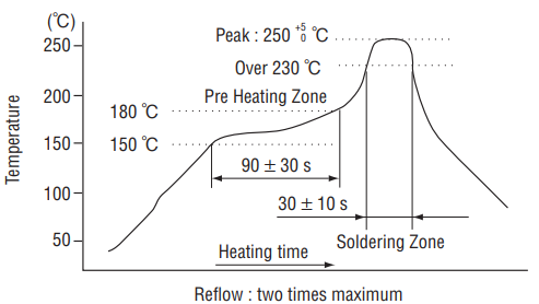
| Soldering heat | Flow : 260 ± 3 °C as the temperature in a pot of molten solder, immer sion from head of ter minal to backside of board, 5 ~ 6 s, two times maximum Reflow : Peak temperature 255 °C (Please refer to the profile below.) Manual soldering:350 ± 10 °C, 3 ~ 4 s |
[ΔR/R ≦ 1%] |
Δ R/R: Change in total resistance
S.S.: Setting stability
S.S.: Setting stability
〈Reflow profile for soldering heat evaluation〉
|
|
MAXIMUM INPUT RATINGS
| Nominal resistance values(Ω) | Resistance code | Maximum input voltage(V) | Maximum wiper current(mA) |
|---|---|---|---|
| 10※ | 100 | 1.00 | 100 |
| 20※ | 200 | 2.00 | 100 |
| 50 | 500 | 3.53 | 70.7 |
| 100 | 101 | 5.00 | 50.0 |
| 200 | 201 | 7.07 | 35.4 |
| 500 | 501 | 11.2 | 22.4 |
| 1k | 102 | 15.8 | 15.8 |
| 2k | 202 | 22.4 | 11.2 |
| 5k | 502 | 35.4 | 7.07 |
| 10k | 103 | 50.0 | 5.00 |
| 20k | 203 | 70.7 | 3.54 |
| 50k | 503 | 112 | 2.24 |
| 100k | 104 | 158 | 1.58 |
| 200k | 204 | 200 | 1.00 |
| 500k | 504 | 200 | 0.40 |
| 1M | 105 | 200 | 0.20 |
| 2M | 205 | 200 | 0.10 |
The products indicated by ※ mark are manufactured upon receipt of order basis.
Part Number Designation
| ST-4 | E | T | A | 200 Ω (201) |
|---|---|---|---|---|
|
Series
ST-4: ST-42: (Rotor groove) minus slot cross slot |
Terminal pins E: Sn-Cu (Lead-free) |
Packaging form T: Taping (Reel) Blank: Bulk in plastic bag |
Terminal shape (Adjust Pos.) A: J-hook (Top adjust) B: Gull wing (Top adjust) C: Through hole pins (Top adjust) D: Gull wing (Rear adjust) F: Through hole pins (Rear adjust) G: J-hook (Side adjust) H: Gull wing (Side adjust) |
Resistance value (Resistance code) |
List of Part Numbers
| Nominal resistance values | 10 Ω*, 20 Ω*, 50 Ω, 100 Ω, 200 Ω, 500 Ω, 1 kΩ, 2 kΩ, 5 kΩ, 10 kΩ, 20 kΩ, 50 kΩ, 100 kΩ, 200 kΩ, 500 kΩ, 1 MΩ, 2 MΩ |
|---|
When ordering, please be sure to include the above nominal resistance value at the end of the part number below. *10 Ω item, 20 Ω item are made to order.
Downloads of chemSHERPA (e.g. for REACH-SVHC surveys) are available below. *Need to log in to download.
| Part No. | Rotor groove | Terminal shape | Adjustment position | Packaging form | Packaging quantity | REACH-SVHC | CAD |
|---|---|---|---|---|---|---|---|
| ST-4ETA | minus slot | J-hook | Top adjust | Taping | 500 pcs./reel |
||
| ST-4EA | minus slot | J-hook | Top adjust | Bulk | 100 pcs./pack | ||
| ST-4ETB | minus slot | Gull wing | Top adjust | Taping | 500 pcs./reel |
||
| ST-4EB | minus slot | Gull wing | Top adjust | Bulk | 100 pcs./pack | ||
| ST-4EC | minus slot | Through hole | Top adjust | Bulk | 100 pcs./pack | ||
| ST-4ETD* | minus slot | Gull wing | Rear adjust | Taping | 500 pcs./reel |
||
| ST-4ED* | minus slot | Gull wing | Rear adjust | Bulk | 100 pcs./pack | ||
| ST-4EF※ | minus slot | Through hole | Rear adjust | Bulk | 100 pcs./pack | ||
| ST-4ETG | minus slot | J-hook | Side adjust | Taping | 500 pcs./reel |
||
| ST-4EG | minus slot | J-hook | Side adjust | Bulk | 100 pcs./pack | ||
| ST-4ETH | minus slot | Gull wing | Side adjust | Taping | 500 pcs./reel |
||
| ST-4EH | minus slot | Gull wing | Side adjust | Bulk | 100 pcs./pack | ||
| ST-42ETA | cross slot | J-hook | Top adjust | Taping | 500 pcs./reel |
||
| ST-42EA | cross slot | J-hook | Top adjust | Bulk | 100 pcs./pack | ||
| ST-42ETB | cross slot | Gull wing | Top adjust | Taping | 500 pcs./reel |
||
| ST-42EB | cross slot | Gull wing | Top adjust | Bulk | 100 pcs./pack | ||
| ST-42EC | cross slot | Through hole | Top adjust | Bulk | 100 pcs./pack | ||
| ST-42ETD* | cross slot | Gull wing | Rear adjust | Taping | 500 pcs./reel |
||
| ST-42ED* | cross slot | Gull wing | Rear adjust | Bulk | 100 pcs./pack | ||
| ST-42EF* | cross slot | Through hole | Rear adjust | Bulk | 100 pcs./pack | ||
| ST-42ETG | cross slot | J-hook | Side adjust | Taping | 500 pcs./reel |
||
| ST-42EG | cross slot | J-hook | Side adjust | Bulk | 100 pcs./pack | ||
| ST-42ETH | cross slot | Gull wing | Side adjust | Taping | 500 pcs./reel |
||
| ST-42EH | cross slot | Gull wing | Side adjust | Bulk | 100 pcs./pack |
*
Rear adjustment type is made to order.
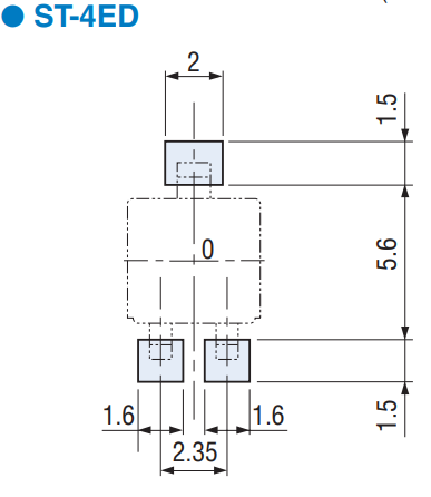
Recommended P.C.B. Pad Outline Dimensions
|
|
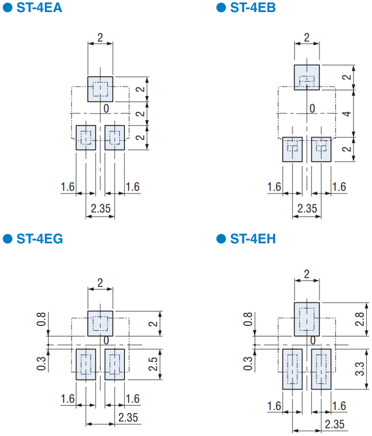
|
|
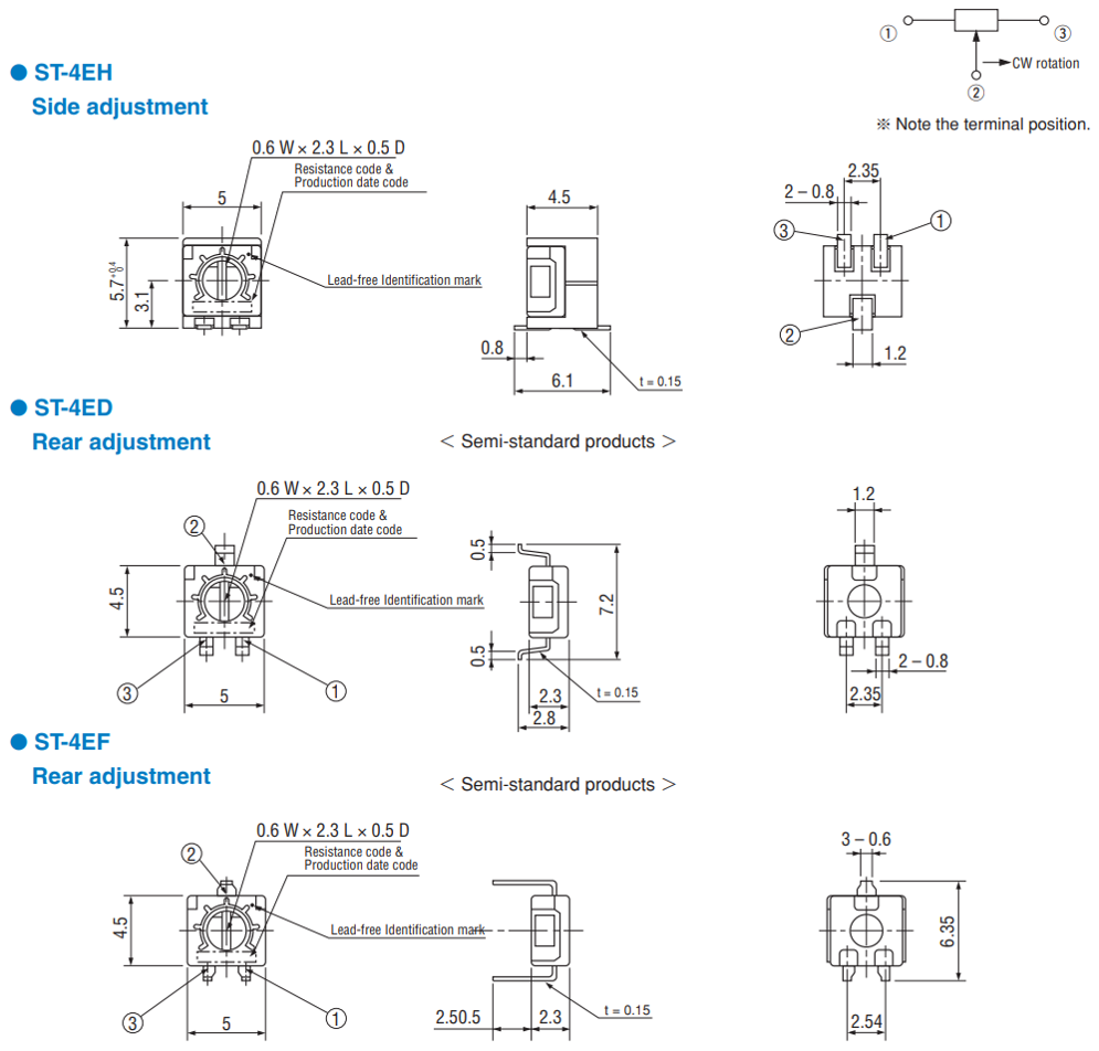
Outline Dimensions
Unless otherwise specified, tolerance : ± 0.3 (Unit: mm)
|
|
Unterlagen
Environmental Data
- ●Die oben genannten Inhalte können ohne vorherige Ankündigung geändert werden.
Produkte
