


Drehgeber RE12

- ●Um einen Kauf zu tätigen, wenden Sie sich an die Verteiler
oder nutzen Sie den stehenden Online-Shops unten.
Verkaufskanal Überprüfen Sie die Verteiler.- VERKAUFSKANALKlicken Sie hier, um den Verteiler zu überprüfen.


Small size, high resolution and low cost
- φ12 mm, High resolution up to 300 P/R
- Cost effective
- Two bearing types to choose from;
Sleeve bearing or ball bearing - Low torque, low inertia
- RoHS compliant
PART NUMBER DESIGNATION
| RE12 | A- | 100- | 100- | 1 |
|---|---|---|---|---|
|
Series name |
Bearing A:Ball bearing |
Resolution (P/R) 100, 200, 300 |
Output phase:“A” Input voltage : 5 V No AMP |
Output connection 1:Cable wire |
LIST OF PART NUMBERS
| Part number | Bearing | Resolution |
|---|---|---|
| RE12A-100-100-1 | Ball Bearing | 100 P/R |
| RE12A-200-100-1 | Ball Bearing | 200 P/R |
| RE12A-300-100-1 | Ball Bearing | 300 P/R |
| RE12C-100-100-1 | Sleeve Bearing | 100 P/R |
| RE12C-200-100-1 | Sleeve Bearing | 200 P/R |
| RE12C-300-100-1 | Sleeve Bearing | 300 P/R |
ELECTRICAL CHARACTERISTICS
| Resolution | 100・200 P/R | 300 P/R |
|---|---|---|
| Photo-sensor maximum current | 50 mA maximum (at 25 °C) | |
| Output wave form | Quasi-sinusoidal | |
| Output signal ※1 | 150 mVp-p minimum | 100 mVp-p minimum |
| Output signal amplitude variation ※2 |
40 % maximum | 50 % maximum |
| Light source | LED | |
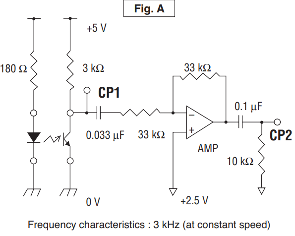
※1:Measured at CP1 as per the Fig. A of ‘MEASUREMENT CIRCUIT’ on the following page. (3 kHz)
※2 : Measured at CP2 as per the Fig. A of ‘MEASUREMENT CIRCUIT’ on the following page. (3 kHz)
⦿MEASUREMENT CIRCUIT
|
|
Mechanical characteristics
| Starting torque | Ball bearing | 0.05 mN·m {0.5 gf·cm} maximum | |
|---|---|---|---|
| Sleeve bearing | 0.4 mN·m {4 gf·cm} maximum | ||
| Inertia | 0.01 g·cm2 maximum | ||
| Shaft loading | Radial | 1.96 N {200 gf} maximum | |
| Axial | 4.9 N {500 gf} maximum | ||
| Net weight | Approx. 10 g | ||
Environmental characteristics
| Operating temp. range | −10 ~ 50 °C |
|---|---|
| Storage temp.range | −20 ~ 80 °C |
| Protection grade | IP40 |
Output signal level & Amplitude variation
|
|
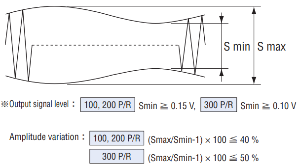
⦿ Criteria
| 項目 | 100・200 P/R | 300 P/R | Measurement point |
|---|---|---|---|
| Output signal level | S min ≧ 0.13 V | S min ≧ 0.08 V | CP1 in ‘MEASUREMENT CIRCUIT’ |
| Amplitude variation | (S max / S min – 1) × 100 ≦ 45 % | (S max / S min – 1) × 100 ≦ 55 % | CP2 in ‘MEASUREMENT CIRCUIT’ |
⦿ MEASUREMENT CIRCUIT
|
|
RELIABILITY TEST
| Test item | Test conditions | ||
|---|---|---|---|
| Vibration | Power OFF | Amplitude : 1.52 mm or 98.1 m/s2(10 G) whichever is smaller. 10 ~ 500 Hz excursion 5 min/cycle, 1 hour each for X, Y, Z, directions. |
|
| Shock | Power OFF | 1 time each in 6 directions (X, Y, Z) at 490 m/s2 (50 G), 11 ms. | |
| High temperature exposure | Power OFF | 80 °C 96 h | (To be measured after leaving samples for 1 h at normal temperature and humidity after the test.) |
| Power ON | 50 °C 96 h | ||
| Low temperature exposure | Power OFF | − 20 °C 96 h | |
| Power ON | − 10 °C 96 h | ||
| Humidity | Power OFF | 40 °C Relative humidity 90 〜 95 % 96 h (To be measured after wiping out moisture and leaving samples for 1 h at normal temperature and humidity after the test.) |
|
| Thermal shock | Power OFF | To be done 10 cycles with the following condition (To be measured after leaving samples for 1 h at normal temperature and humidity after the test.) 80 °C 1 h、-20 °C 1 h |
|
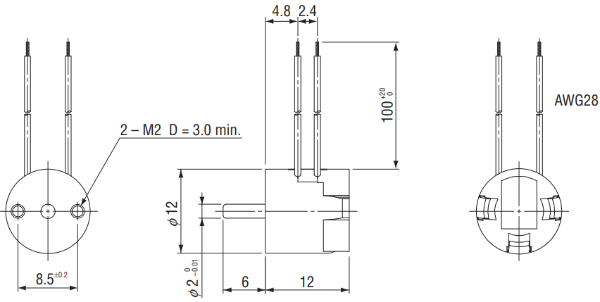
OUTLINE DIMENSIONS
Unless otherwise specified, tolerance : ± 0.4 (Unit : mm)
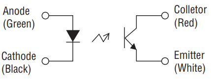
INTERNAL CIRCUIT
|
|
MEASUREMENT CIRCUIT
|
|
Unterlagen
- ●Die oben genannten Inhalte können ohne vorherige Ankündigung geändert werden.
Produkte
