


Druckaufnehmer (mit Verstärker) PA-858

- ●Um einen Kauf zu tätigen, wenden Sie sich an die Verteiler
oder nutzen Sie den stehenden Online-Shops unten.
Verkaufskanal Überprüfen Sie die Verteiler.- VERKAUFSKANALKlicken Sie hier, um den Verteiler zu überprüfen.


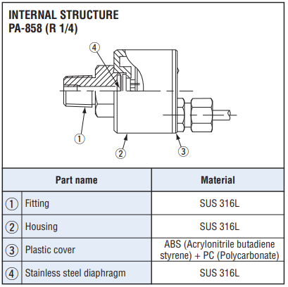
Pressure transducer with amp. PA-858
- High corrosion resistance and drip-proof construction
Pressure port attachment made of SUS 316L
Proven IP65 grade gauge body (IP65 in accordance with IEC) - Absolute pressure type and compound pressure type
which can control negative to positive pressure with only
a single pressure gauge are all in line - Three standard types of joint are provided
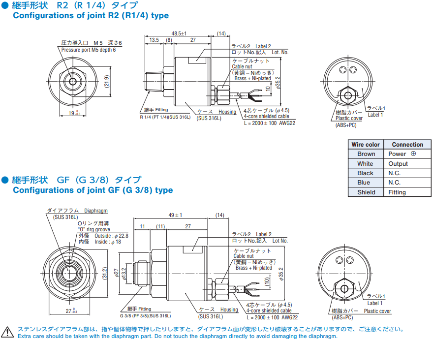
R2 : R 1/4 (M 5 female screw)
GF : G 3/8 with flash diaphragm
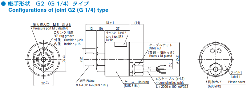
G2 : G 1/4 (M 5 female screw)
|
|
Model Number Designation
| PA-858 - | 102 R | R2 |
|---|---|---|
|
Series name |
Rated pressure range/Pressure reference 102G:0 ~ 100 kPa(Gauge) 352G:0 ~ 350 kPa(Gauge) |
Fitting R2:R 1/4 with M 5 female screw |
List of model numbers
| Model Number | Pressure reference | Rated pressure kPa | Maximum pressure kPa | Break-down pressure kPa | Fitting | CAD |
|---|---|---|---|---|---|---|
| PA-858-102G-R2 | Gauge | 100 | 200 | 300 | R2 (R 1/4) | |
| PA-858-102G-GF | Gauge | 100 | 200 | 300 | GF (G 3/8) | |
| PA-858-102G-G2 | Gauge | 100 | 200 | 300 | G2 (G 1/4) | |
| PA-858-352G-R2 | Gauge | 350 | 700 | 1050 | R2 (R 1/4) | |
| PA-858-352G-GF | Gauge | 350 | 700 | 1050 | GF (G 3/8) | |
| PA-858-352G-G2 | Gauge | 350 | 700 | 1050 | G2 (G 1/4) | |
| PA-858-103G-R2 | Gauge | 1000 | 2000 | 3000 | R2 (R 1/4) | |
| PA-858-103G-GF | Gauge | 1000 | 2000 | 3000 | GF (G 3/8) | |
| PA-858-103G-G2 | Gauge | 1000 | 2000 | 3000 | G2 (G 1/4) | |
| PA-858-102V-R2 | Gauge | − 100 | 200 | 300 | R2 (R 1/4) | |
| PA-858-102V-GF | Gauge | − 100 | 200 | 300 | GF (G 3/8) | |
| PA-858-102V-G2 | Gauge | − 100 | 200 | 300 | G2 (G 1/4) | |
| PA-858-302R-R2 | Gauge | − 100 ~ 300 | 600 | 900 | R2 (R 1/4) | |
| PA-858-302R-GF | Gauge | − 100 ~ 300 | 600 | 900 | GF (G 3/8) | |
| PA-858-302R-G2 | Gauge | − 100 ~ 300 | 600 | 900 | G2 (G 1/4) | |
| PA-858-102A-R2 | Absolute | 100 (abs) | 200 (abs) | 300 (abs) | R2 (R 1/4) | |
| PA-858-102A-GF | Absolute | 100 (abs) | 200 (abs) | 300 (abs) | GF (G 3/8) | |
| PA-858-102A-G2 | Absolute | 100 (abs) | 200 (abs) | 300 (abs) | G2 (G 1/4) |
Standard specifications
- Unless otherwise specified, the specs are defined at an ambient temperature of 25 ± 5 °C and excitation voltage of 24 V DC, load resistance of 250 Ω.
| Operating temp. range | − 20 ~ 70 °C |
|---|---|
| Compensated temp. range | 0 ~ 50 °C |
| Operating humidity | 35 ~ 85%RH(No condensation) |
| Storage temp. | − 20 ~ 80 °C(Atmospheric pressure, humidity 65 %RH maximum) |
| Pressure medium | Corrosive gases/liquids compatible with SUS 316L |
| Insulation resistance | 100 (500 V DC)MΩ minimum |
| Dielectric strength | 500 V AC, 60 s(Leakage current 1 mA maximum) |
| Sealed liquid | Silicone oil |
| Pressure port | R 1/4、G 3/8(Flash diaphragm),G 1/4 ※ 1 |
| Net weight | R2 : Approx. 165g, GF : Approx. 180g, G2 : Approx. 170g |
| Protection grade | IP65 |
| Supply voltage |
24 ± 10 % V DC(Including ripple percentage) |
※ 1 : An “O” ring provided. (G 3/8 : P18, G 1/4 : P15)
Analog output
- Unless otherwise specified, the specs are defined at an ambient temperature of 25 ± 5 °C and excitation voltage of 24 V DC, load resistance of 250 Ω.
| Pressure range | 102G | 352G | 103G | 102V | 302R | 102A |
|---|---|---|---|---|---|---|
| Output current |
4 ~ 20 mA | |||||
| Zero current | 4 ± 0.2 mA | 8 ± 0.2 mA | 4 ± 0.2 mA | |||
| Span current | 16 ± 0.2 mA | |||||
| Load resistance | 0 ~ 500 Ω | |||||
| Linearity/Hysteresis | ± 0.5 | |||||
| Thermal error | ZERO:± 0.06 %F.S./°C SPAN:± 0.06 %F.S./°C | |||||
| Response | Approx. 2 ms | |||||
| Gravitational effect (From horizontal position to vertical position) |
± 0.3%F.S. | ± 0.1%F.S. | ± 0.05%F.S. | ± 0.3%F.S. | ± 0.1%F.S. | ± 0.3%F.S. |
Environment Characteristics
| Test item | Test conditions (At 25 ± 5 °C) | Permissible change |
|---|---|---|
| Vibration | 10 ~ 500 Hz, 1.5 mm maximum/98.1 m/s2, 3 directions for 2 hours each |
Zero current, Span current: ± 1 %F.S. maximum each |
| Shock | 490 m/s2、3 directions for 3 times each | |
| Pressure cycling | 0 〜Rated pressure/Rated pressure range 106 cycle | |
| Moisture resistance | 40 °C, 90 ~ 95 %RH, 240 hrs. |
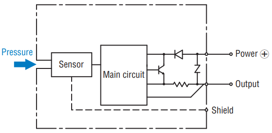
INTERNAL ELECTRICAL SCHEMATICS
|
|
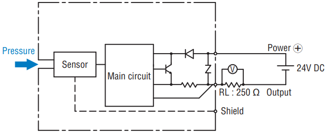
RECOMMENDED EXTERNAL SCHEMATICS
|
|
Outline Dimensions
Unterlagen
- ●Die oben genannten Inhalte können ohne vorherige Ankündigung geändert werden.
Produkte
